

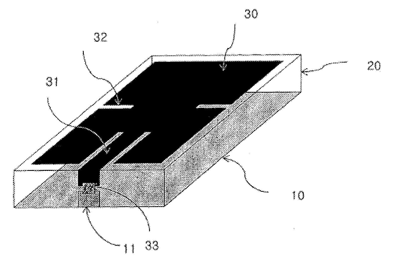
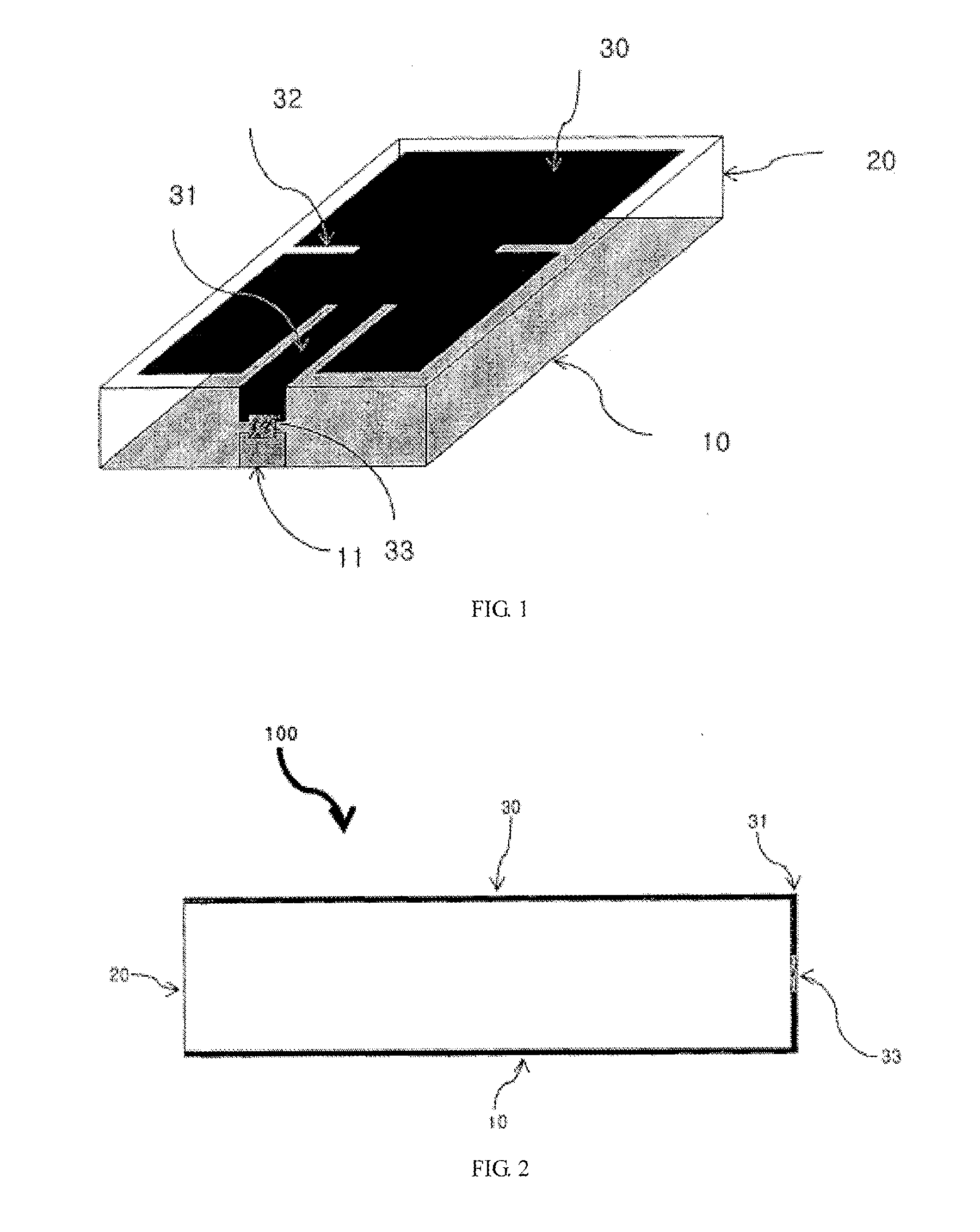
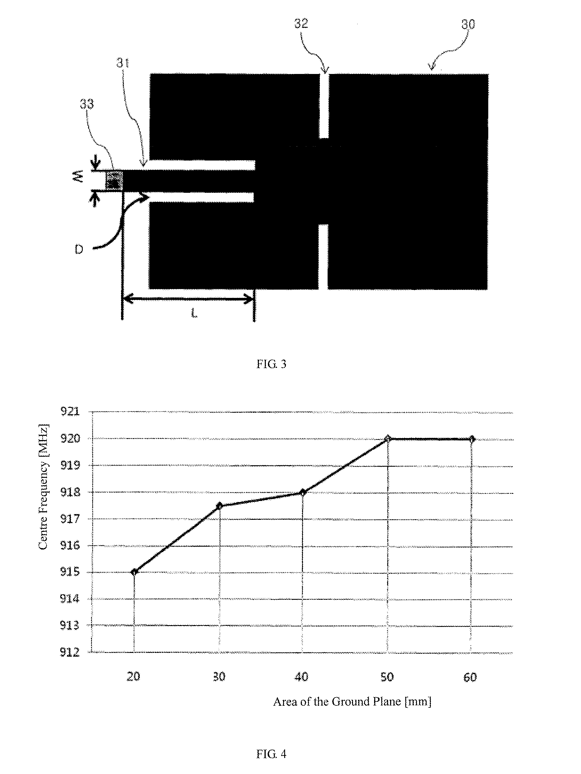
Miniaturized Radio-Frequency Identification Tag and Microstrip Patch Antenna Thereof
a radio frequency identification and microstrip technology, applied in the structure of radiating elements, instruments, resonant antennas, etc., can solve the problems of unstable identification rate of common tags at different positions, inconvenient mass production, and inability to ensure electric power required by the driving of rfit chips, so as to achieve stable identification rates in different positions and the effect of not lowering the performance of the antenna
- Summary
- Abstract
- Description
- Claims
- Application Information
AI Technical Summary
Benefits of technology
Problems solved by technology
Method used
Image

Examples
Embodiment Construction
[0031]The present invention will be further illustrated hereinafter in conjunction with the specific embodiments. The technicians in the field can easily understand other advantages and functions of the present invention according to the contents disclosed by the description. The present invention can also be implemented or applied through other different embodiments. Various modifications or changes can be made to the details of the description without deviation from the aims of the present invention according to different views and applications.
[0032]Radio frequency identification technology is a technology wherein objects are identified by attaching an electric tag onto various objects and identifying the inherent ID of the objects through wireless means. The radio frequency identification system applies to various bands in the range from the 125 kHz frequency band to 5.8 GHz microstrip according to the applicable fields.
[0033]Recently, in fields, including logistics circulation ...
PUM
 Abstract
Description
Claims
Application Information