Lens module with low chromatic aberration

a technology of chromatic aberration and lens module, applied in the field of lenses modules, can solve the problems of increasing the cost of the lens module module, and the type of lens module usually has poor chromatic aberration correction properties

Inactive Publication Date: 2013-02-21
FOSHAN PREMIER SCI & TECH CO LTD +1
View PDF5 Cites 113 Cited by
  • Summary
  • Abstract
  • Description
  • Claims
  • Application Information

AI Technical Summary

Benefits of technology

[0004]In order to improve image quality, lens modules usually include a number of lenses. One typical lens module includes a first lens and a second lens both made of plastics in an order from an object side to an image side. This type of lens module usually has poor chromatic aberration correction properties because plastic has a narrow range of chromatic dispersion. Another typical lens module includes a first lens and a second lens both made of glass by grinding, which is costly, in an order from an object side to an image side. This type of lens module usually has high chromatic aberration correction properties but increases the cost of the lens module module.

Problems solved by technology

This type of lens module usually has poor chromatic aberration correction properties because plastic has a narrow range of chromatic dispersion.
This type of lens module usually has high chromatic aberration correction properties but increases the cost of the lens module module.

Method used


Image

  • Lens module with low chromatic aberration
  • Lens module with low chromatic aberration
  • Lens module with low chromatic aberration

Examples


example 1

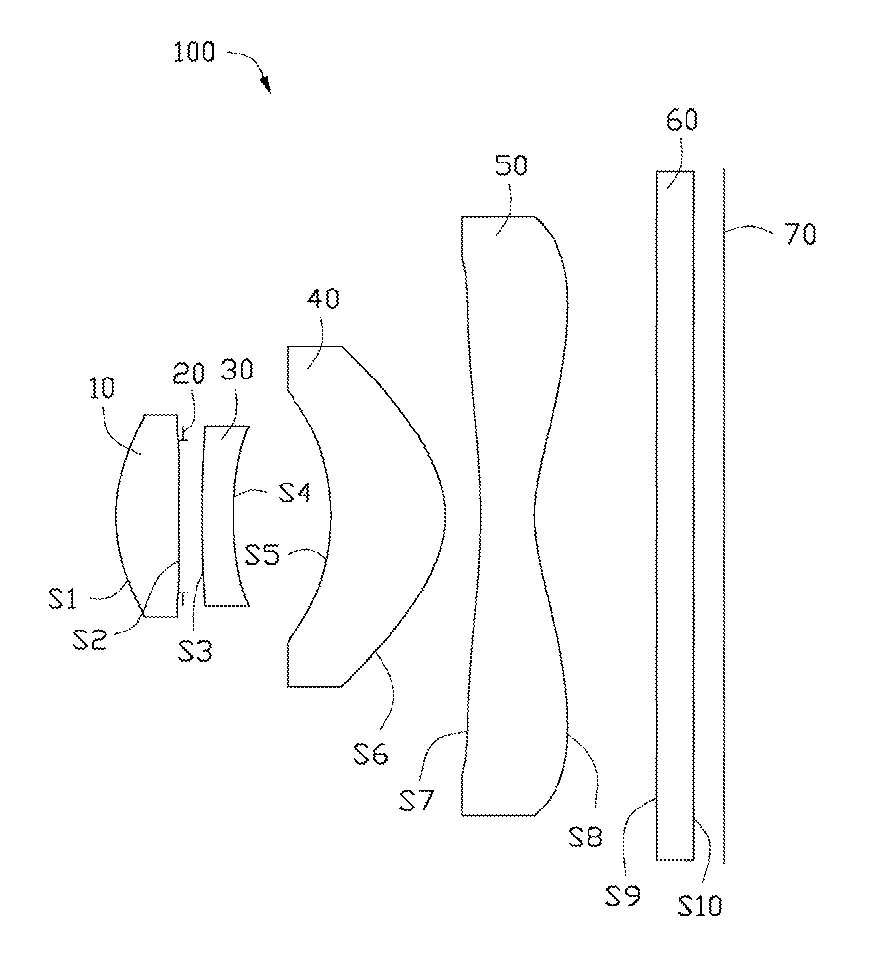
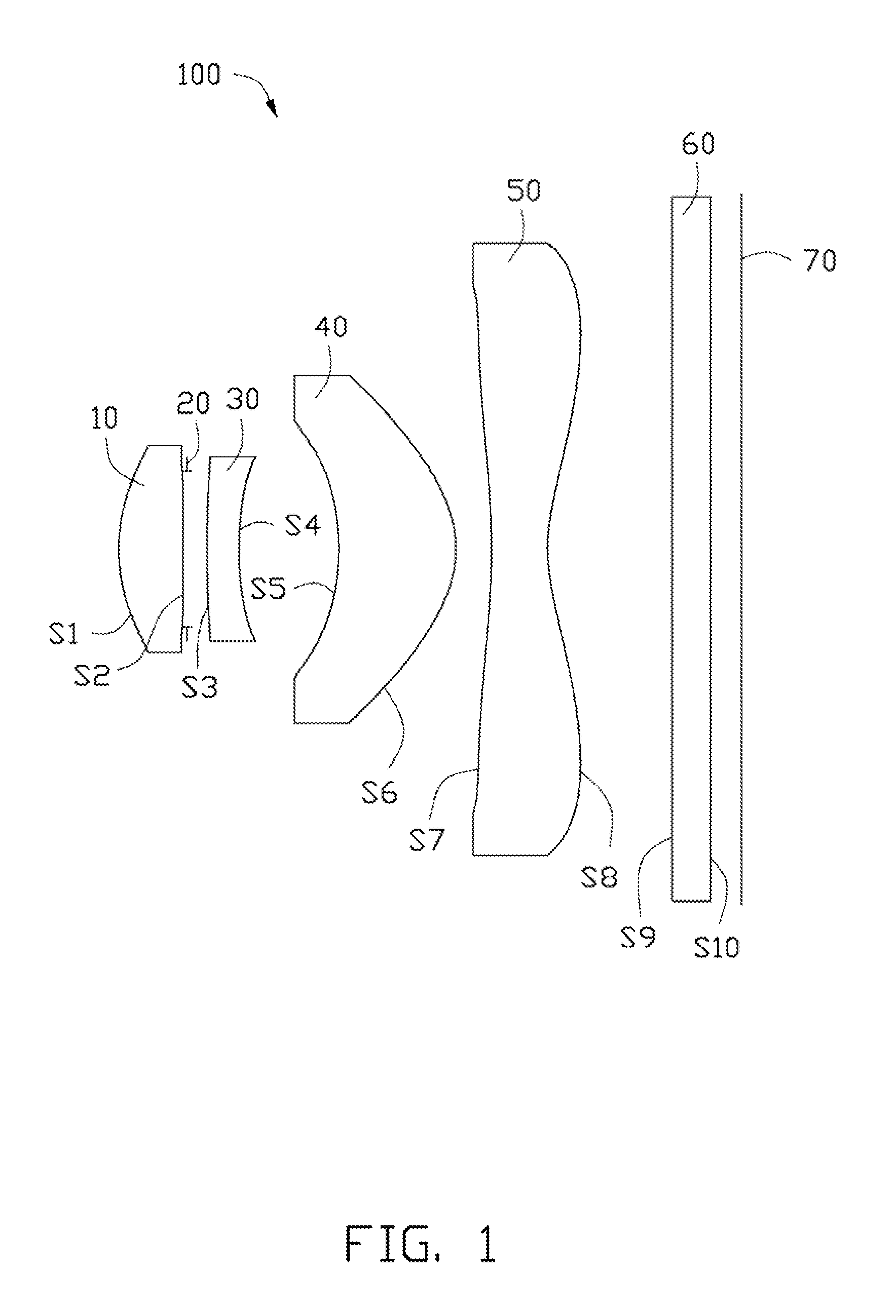
[0037]The lens module 100 of a first embodiment satisfies the tables 1-3, wherein F1=2.97 mm, F2=−6.86 mm, F3=2.22 mm, F4=−2.05 mm, TTL=4.84 mm; Vd1−Vd2=54.92, F1 / F=0.72, and F / TTL=0.85.

TABLE 1surfacetypeR (mm)D (mm)NdVdKS1aspherical1.433910.5121.49781.56−0.872S2aspherical43.52930.024——1.002aperture stopflatInfinity0.171———S3aspherical11.21570.2541.60726.64−744.858S4aspherical3.011240.801——6.304S5aspherical−1.9670.9421.54356.8 −0.411S6aspherical−0.8750.286——−3.131S7aspherical−5.9550.4461.53155.7 −4.127S8aspherical1.370921.000——−10.526S9flatInfinity0.3101.51764.17—S10flatInfinity0.094———image planeflatInfinity————

TABLE 2A2A4A6A8A10S1 1.5257E−024.45020E−02−2.28525E−013.22734E−01−2.89938E−01S2−3.41824E−02−1.6418E−01 5.33581E−01−1.3403E+00 1.10061+00S3 6.83487E−02−5.6552E−02−9.02450E−022.73556E−01−1.98698E−01S4 5.96129E−029.82812E−02−2.39474E−014.49993E−01−2.56024E−01S5−7.88085E−02−5.9641E−02 2.14626E−01−2.6615E−01 1.23780E−01S6−1.53571E−019.74889E−02−4.89157E−021.82063E−02−3.06305E−03S...

example 2

[0039]The lens module 100 in accordance with a second embodiment satisfies the tables 4-6, wherein F1=3.17 mm, F2=−7.29 mm, F3=2.27 mm, and F4=−2.33 mm, TTL=4.98 mm; Vd1−Vd2=47.76, F1 / F=0.77, and F / TTL=0.83.

TABLE 4surfaceTypeR (mm)D (mm)NdVdKS1aspherical1.604380.5121.55371.7−0.798S2aspherical16.64590.024——150.947aperture stopFlatInfinity0.171———S3aspherical6.338430.2541.63323.2423.477S4aspherical2.628320.801——2.968S5aspherical−1.94640.9421.54356.8 −8.02S6aspherical−0.88270.286——−3.068S7aspherical−7.1210.4461.53155.7 −197.741S8aspherical1.532251.092——−11.010S9FlatInfinity0.3101.51764.17—S10FlatInfinity0.140———imageFlatInfinity————plane 70

TABLE 5ABCDES19.05720E−031.77254E−02−1.35398E−011.83509E−01−1.52003E−01S2−2.93450E−02−2.69649E−019.85391E−01−2.0688E+001.58640+00S3−3.56004E−023.71676E−02−2.44704E−02−2.3109E−013.92838E−01S41.95824E−021.25622E−01−2.93993E−014.44073E−01−1.84731E−01S5−9.25653E−02−5.32063E−022.03386E−01−2.6030E−011.26063E−01S6−1.51832E−017.66839E−02−3.33611E−021.15582E−...


PUM


Abstract

Provided is a lens module for imaging an object on an image plane. In the order from the object side to the image side of the lens module, the lens module includes a first lens made of glass and having positive refraction power, a second lens made of plastic and having negative refraction power, a aperture stopper, a third lens having positive refraction power, and a fourth lens having negative refraction power. The lens module satisfies the following formula: Vd1−Vd2≧35; wherein, Vd1 is the Abbe number of the first lens in d light and Vd2 is the Abbe number of the second lens in the d light.

Description

BACKGROUND[0001]1. Technical Field[0002]The present disclosure relates to lens modules and, particularly, to a lens module with low chromatic aberration.[0003]2. Description of Related Art[0004]In order to improve image quality, lens modules usually include a number of lenses. One typical lens module includes a first lens and a second lens both made of plastics in an order from an object side to an image side. This type of lens module usually has poor chromatic aberration correction properties because plastic has a narrow range of chromatic dispersion. Another typical lens module includes a first lens and a second lens both made of glass by grinding, which is costly, in an order from an object side to an image side. This type of lens module usually has high chromatic aberration correction properties but increases the cost of the lens module module.[0005]Therefore, it is desirable to provide a lens module which can overcome the limitations described above.BRIEF DESCRIPTION OF THE DRA...

Claims


Application Information

Patent Timeline
Patent Type & Authority Applications(United States)
IPC IPC(8): G02B13/18G02B9/34
CPCG02B13/004
Inventor YIN, WEI
Owner FOSHAN PREMIER SCI & TECH CO LTD
Why Eureka
Try Eureka