Arthrodesis implant

a technology of orthopaedic implants and articular bones, which is applied in the field of medical implants, can solve the problems of corns, corns, corns, etc., and achieve the effects of reducing the risk of fracture, and improving the quality of li

Active Publication Date: 2013-03-14
ADSM
View PDF0 Cites 60 Cited by
  • Summary
  • Abstract
  • Description
  • Claims
  • Application Information

AI Technical Summary

Benefits of technology

[0009]The present invention proposes an implant having a structure suited to bestowing upon the implant both flexibility and rigidity allowing it to ensure, once implanted, three-dimensional stability for the unit made up of the first phalanx, the second phalanx and the implant, at least during the period necessary for osseous fusion between the two phalanges, that is to say for a duration of approximately six weeks. The implant as claimed in the invention thus allows the organ treated to have its natural anatomy restored, in particular the natural angle between the two bones or phalanges fused together again in this manner.

Problems solved by technology

Certain pathologies, such as Hallux Valgus or metatarsalagias (or claw toes), induce deformation of the toes in the foot: in particular, two phalanges adjacent to a toe do not keep their natural alignment and between them form an angle permanently deforming the toe.
Said pathologies cause pain in the front of the foot, corns, and functional difficulties: the patient finds it difficult to walk correctly: it may also be difficult for him to wear shoes.
However, existing implants do not always ensure the necessary stability of the unit, made up by the first phalanx, the second phalanx and the implant, in the three spatial directions for the necessary time after implantation, until the two phalanges have fused together.
But, if the implant or one or both of the phalanges is displaced during said lapse of time, the two phalanges will be fused together incorrectly and the treatment will fail.

Method used


Image

  • Arthrodesis implant
  • Arthrodesis implant
  • Arthrodesis implant

Examples


Embodiment Construction

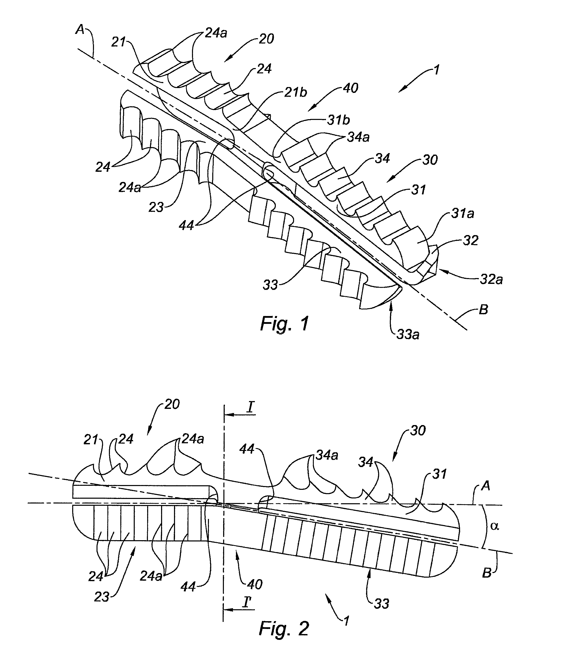
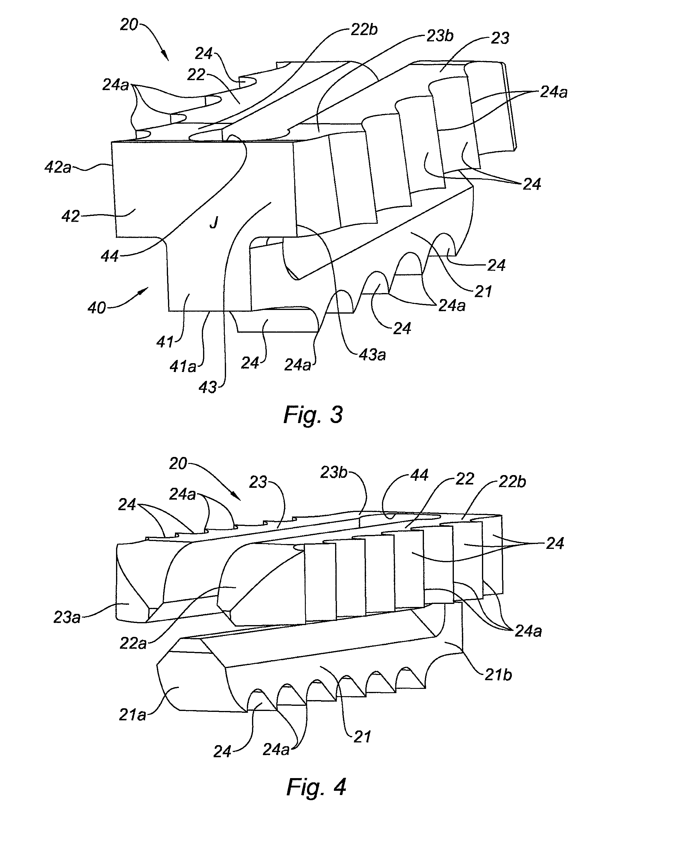
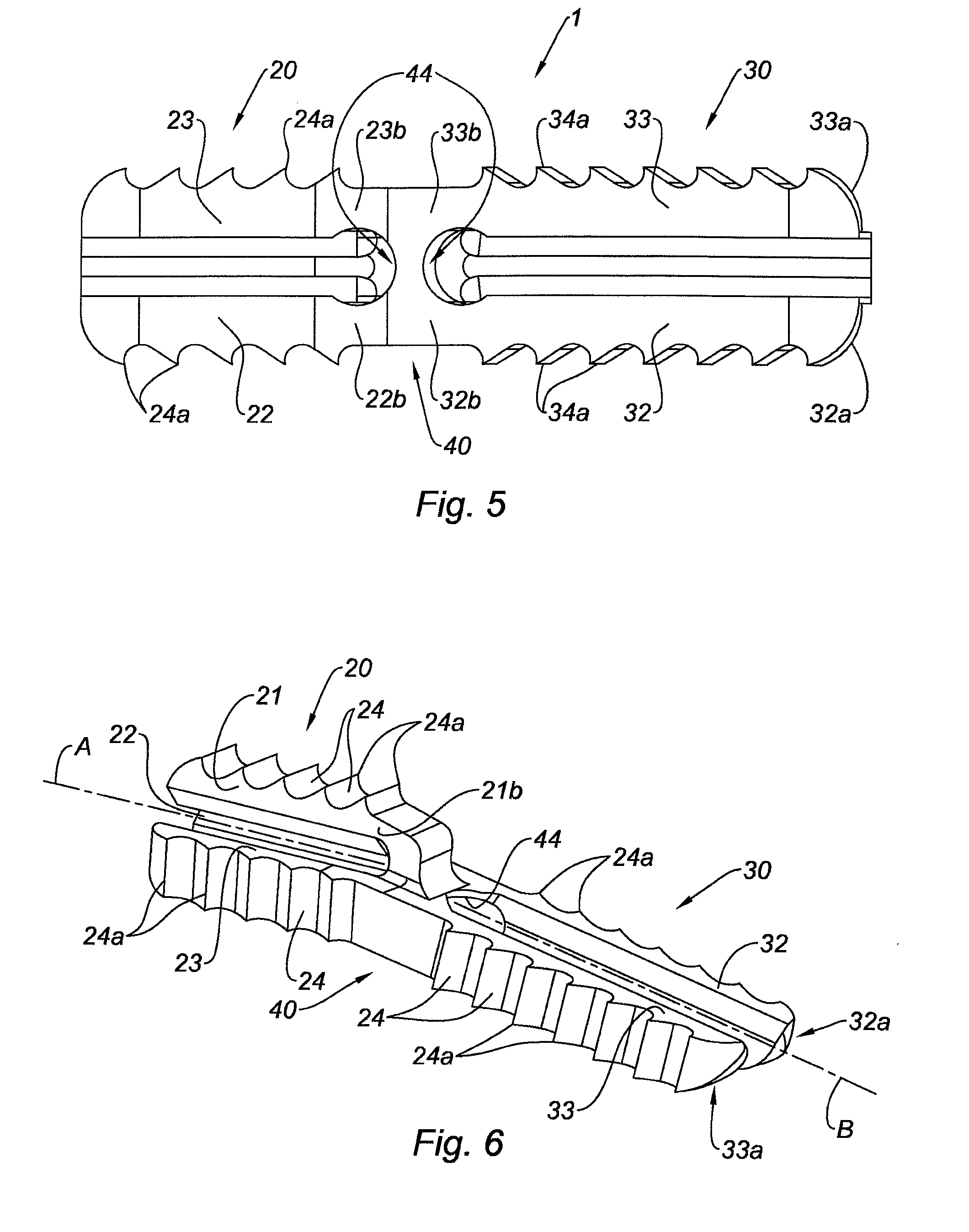
[0029]FIGS. 1 to 3 show an implant 1 as claimed in the invention for realizing an arthrodesis. The implant 1 includes a first part 20, with an elongated shape overall, having a longitudinal axis A, a second part 30, also with an elongated shape overall and having a longitudinal axis B, and a central core 40 connecting the first part 20 to the second part 30. In the example shown, the longitudinal axis A and the longitudinal axis B form between them an angle α: said angle α can vary by about 0 to 30°, for example from 10 to 20°, in particular in order to adjust the implant of the invention to the anatomy of the part of the human body to be treated, for example the foot or the hand. In one embodiment not shown, the angle α can be zero: in such a case, the first part and the second part are located in line with one another.

[0030]As can be seen in FIG. 3, the central core 40 is a solid body, the cross section of which through the plane II′ (see FIG. 2) perpendicular to the longitudinal ...


PUM

PropertyMeasurementUnit
angleaaaaaaaaaa
angleaaaaaaaaaa
angleaaaaaaaaaa

Abstract

The invention relates to an implant (1) for osseous fusion between two bones, including a first portion (20) having a longitudinal axis A, for being inserted in the first bone and including a first means (24) for attaching said implant in said first bone, and a second portion (30) having a longitudinal axis B, for being inserted in the second bone and including a second means (34) for attaching said implant in said second bone, said first and second portions (20, 30) being connected by a central core (40), said central core being a solid body, the cross-section of which, in a plane perpendicular to said longitudinal axis A, has the shape of a star having at least three points (41, 42, 43), said first portion having three tabs (21, 22, 23), each tab extending along said longitudinal axis A from the free end (41a, 42a, 43a) of one of the points of said central core.

Description

TECHNICAL FIELD[0001]The present invention concerns a medical implant intended to connect two bones together. In particular, the invention concerns an articulated orthopedic implant for the foot or the hand, intended to connect and attach two adjacent phalanges together.BRIEF DESCRIPTION OF RELATED ART[0002]Certain pathologies, such as Hallux Valgus or metatarsalagias (or claw toes), induce deformation of the toes in the foot: in particular, two phalanges adjacent to a toe do not keep their natural alignment and between them form an angle permanently deforming the toe. Such deformation can take place in a vertical plane, and the patient then suffers from metatarsalgia; the toe adopts a “claw” configuration in which it is permanently tucked under. Alternatively, the deformation can take place in a horizontal plane; the patient then suffers from Hallux Valgus: the toe, in particular the big toe, forms a protuberance on the outside of the foot.[0003]Said pathologies cause pain in the f...

Claims


Application Information

Patent Timeline
Patent Type & Authority Applications(United States)
IPC IPC(8): A61F2/42
CPCA61F2230/0004A61F2/42A61F2230/0052A61F2230/006A61F2310/00011A61B17/7225A61B17/7266A61B17/7283A61B17/7291A61F2/4225A61F2/4241A61F2002/30062A61F2002/30112A61F2002/30171A61F2002/30172A61F2002/30181A61F2002/30571A61F2002/30594A61F2002/30622A61F2002/30904A61F2002/423A61F2002/4243A61F2210/0004A61F2230/005A61F2002/4228
Inventor AVEROUS, CHRISTOPHECERMOLACCE, CHRISTOPHEDETERME, PATRICEDIEBOLD, PATRICEGUILLO, STEPHANEROCHER, HUBERTROY, CHRISTOPHE
Owner ADSM
Why Eureka
Try Eureka