

Cover tape
- Summary
- Abstract
- Description
- Claims
- Application Information
AI Technical Summary
Benefits of technology
Problems solved by technology
Method used
Image

Examples
example 1
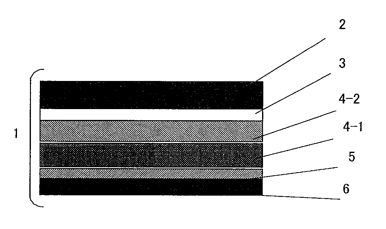
[0097][(a-1) m-LLDPE] polymerized using a metallocene was used as a resin ingredient, kneaded at 200° C. using single screw extruder having a 40 mm-bore, and extruded through a T-die at a line rate of 20 m / min to obtain a 40 μm-thick intermediate film. After coating a surface of a 12 μm-thick biaxially drawn polyester film with a polyester anchor coating agent by a gravure method, the above intermediate film [(a-1) m-LLDPE] was applied to obtain a laminated film comprising a biaxially drawn polyester layer and a m-LLDPE layer. Next, the m-LLDPE surface of the film was subjected to a corona treatment, then [(c-1) resin], which was dissolved in cyclohexane, was applied to the corona treated surface by a gravure method such that the thickness after drying would be 0.8 μm to thereby form a peeling layer. Further, as a heat seal layer on the coated surface of the peeling layer, the butyl methacrylate and methyl methacrylate random copolymer [(d-1) acrylic resin] and [(e-1) inorganic fill...
example 2
[0098]As shown in Table 1, the electrically conductive material (c-14) was added to the peeling layer at 400 parts by mass to 100 parts of the resin, and other than the compounding ratio and composition listed in Table 1, a cover tape was produced in the same manner as in Example 1.
example 10
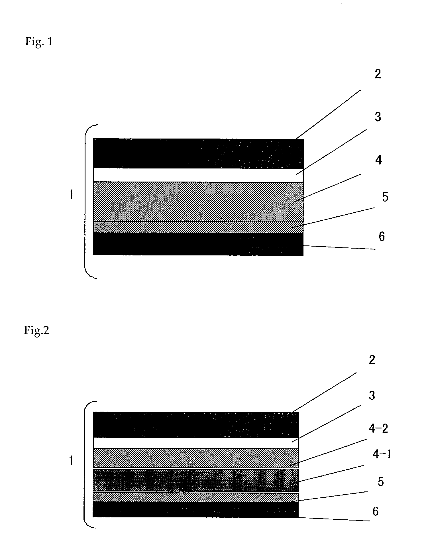
[0103][(a-1) m-LLDPE] polymerized using a metallocene was used as a resin ingredient, kneaded at 200° C. using single screw extruder having a 40 mm-bore, and extruded through a T-die at a line rate of 20 m / min to obtain a 40 μm-thick intermediate film. After coating a surface of a 12 μm-thick biaxially drawn polyester film with a polyester anchor coating agent by a gravure method, the above intermediate film [(a-1) m-LLDPE] was applied to obtain a laminated film comprising a biaxially drawn polyester layer and a m-LLDPE layer. Next, the m-LLDPE surface of the film was subjected to a corona treatment, then [(c-1) resin], which was dissolved in cyclohexane, was applied to the corona treated surface by a gravure method such that the thickness after drying would be 1 μm to thereby form a peeling layer. Further, as a heat seal layer on the coated surface of the peeling layer, the butyl methacrylate and methyl methacrylate random copolymer [(d-1) acrylic resin], [(d-4) electrically conduc...
PUM
| Property | Measurement | Unit |
|---|---|---|
| Temperature | aaaaa | aaaaa |
| Temperature | aaaaa | aaaaa |
| Time | aaaaa | aaaaa |
Abstract
Description
Claims
Application Information