Connector for lifelines

a technology of lifelines and connectors, applied in the direction of safety belts, manufacturing tools, mechanical equipment, etc., can solve the problem of no fall protection for workers

Active Publication Date: 2013-05-02
D B IND
View PDF1 Cites 40 Cited by
  • Summary
  • Abstract
  • Description
  • Claims
  • Application Information

AI Technical Summary

Problems solved by technology

If a fall event occurs during that period

Method used


Image

  • Connector for lifelines
  • Connector for lifelines
  • Connector for lifelines

Examples


Embodiment Construction

[0023]In the following detailed description, reference is made to the accompanying drawings, which form a part hereof, and in which is shown by way of illustration specific embodiments in which the inventions may be practiced. These embodiments are described in sufficient detail to enable those skilled in the art to practice the invention, and it is to be understood that other embodiments may be utilized and that changes may be made without departing from the spirit and scope of the present invention. The following detailed description is, therefore, not to be taken in a limiting sense, and the scope of the present invention is defined only by the claims and equivalents thereof.

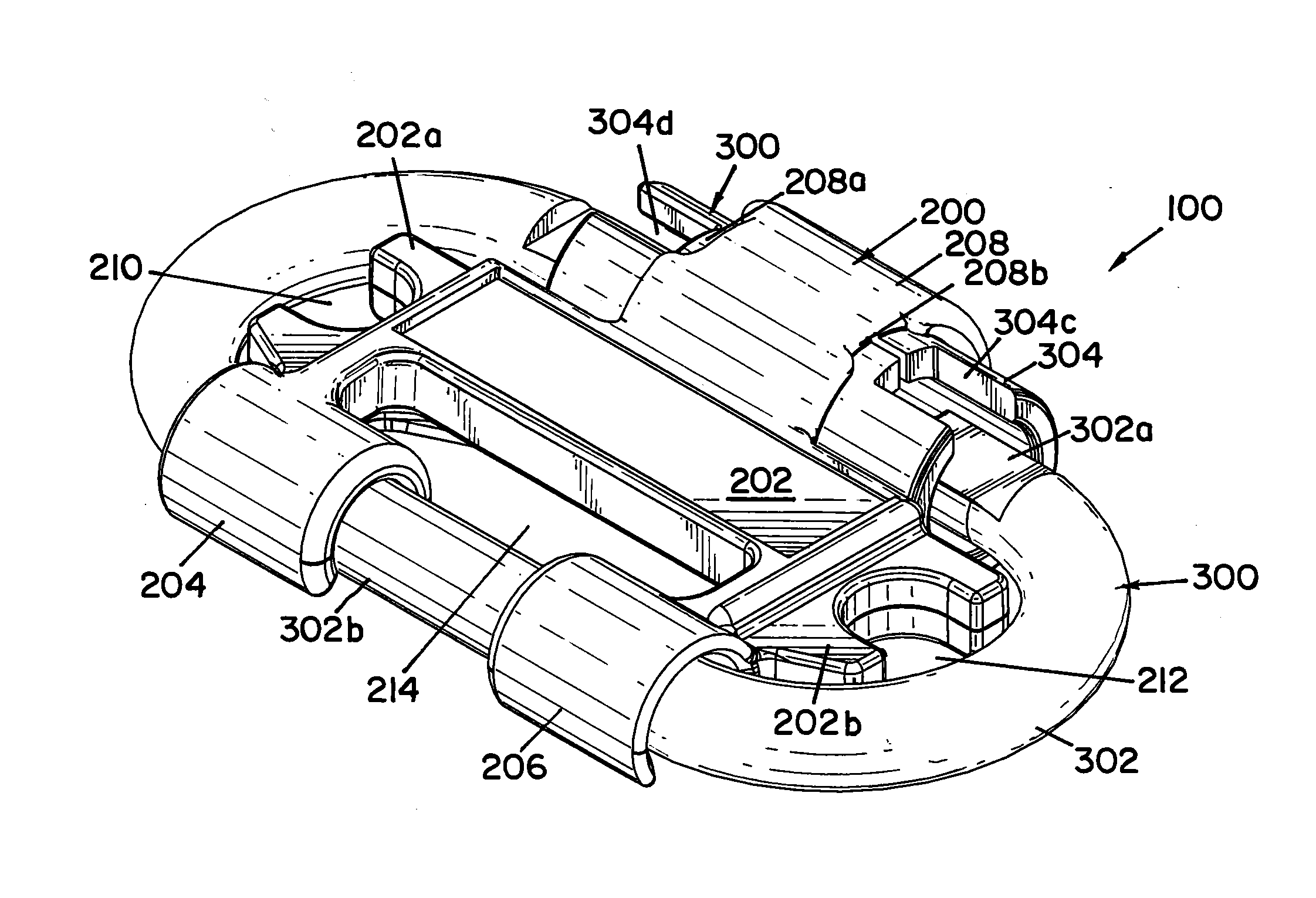
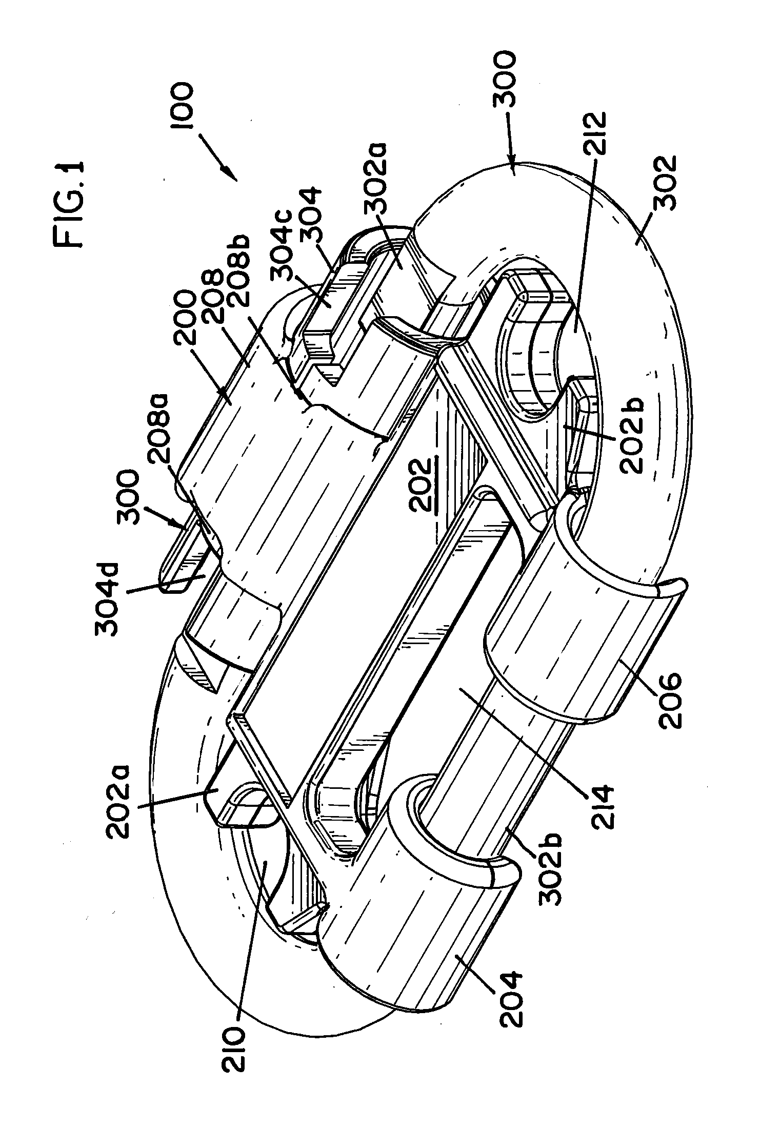
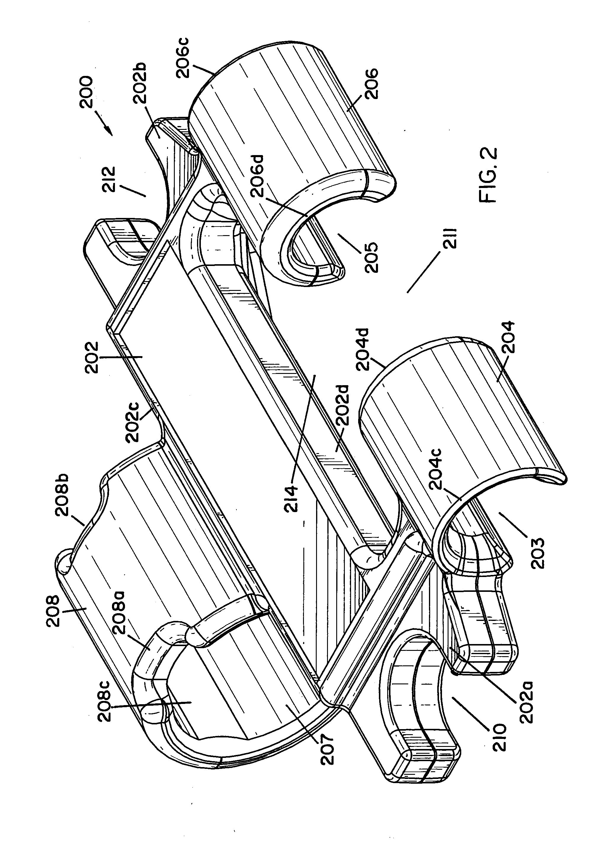
[0024]Embodiments of the present invention provide a connector to connect two lifelines to a safety harness. In embodiments, a carabiner and an insert are used to form the connector. The connector is configured to space the lifelines apart from each other to help avoid entanglements between the two lifelines ...


PUM

PropertyMeasurementUnit
Lengthaaaaaaaaaa
Shapeaaaaaaaaaa
Widthaaaaaaaaaa

Abstract

A connector that includes a carabiner and an insert is provided. The base of the insert has a length that extends between a first end and a second end and a width that extends between a first side edge and a second side edge. A barrel connector of the insert centrally extends from the first side edge of the base. The barrel connector receives a barrel of a gate of the carabiner. A first ear extends from the second side edge of the base proximate the first end of the base. The first ear includes a first carabiner retaining channel that selectively engages a first portion of the carabiner. A second ear extends from the second side edge of the base proximate the second end of the base. The second ear includes a second carabiner retaining channel that selectively engages a second portion of the carabiner.

Description

CROSS-REFERENCE TO RELATED APPLICATIONS[0001]This application claims priority to U.S. Provisional Application Ser. No. 61 / 552,051, same title herewith, filed on Oct. 27, 2011, which is incorporated in its entirety herein by reference.BACKGROUND[0002]Safety harnesses are typically used in work areas that subject workers to the risk of falling. In some high risk areas, a safety harness is coupled to a lifeline that is in turn coupled to a support structure. If a fall event should occur, the lifeline coupled to the support structure limits the fall of the worker donning the safety harness to prevent injuries to the worker. In some work environments, it is necessary for the worker to move about from a first area to a second area. It is common in this situation that the worker will have to disconnect the lifeline from a first support structure in the first area and connect to a second support structure in the second area when moving from the first area to the second area. Hence, there is...

Claims


Application Information

Patent Timeline
IPC IPC(8): F16B45/02
CPCF16B45/02Y10T24/45372Y10T29/49947A62B35/0037F16B45/037F16B45/022F16B45/027
Inventor SCHLANGEN, DAVID A.WADDELL, ROBERT S.GAMACHE, GABRIEL G.
Owner D B IND
Why Eureka
Try Eureka