Handling mechanism and punching machine using the same

Active Publication Date: 2013-05-16
SHENZHENSHI YUZHAN PRECISION TECH CO LTD +1
View PDF1 Cites 3 Cited by
  • Summary
  • Abstract
  • Description
  • Claims
  • Application Information

AI Technical Summary

Benefits of technology

The present disclosure relates to a handling mechanism used in a punching machine. The technical effect of the patent is to provide a more efficient and cost-effective handling mechanism that can convey workpieces along two perpendicular directions without the need for a robot. The conventional handling mechanism is limited in its ability to slide along one direction and requires a robot to achieve the desired movement. The present disclosure proposes a new handling mechanism that can clamp and position the workpiece on the lower mold and allow the upper mold to punch the workpiece on the support table, thereby improving the efficiency of the punching process.

Problems solved by technology

However, the robot has a complicated structure, and the cost of the robot is relatively high.

Method used


Image

  • Handling mechanism and punching machine using the same
  • Handling mechanism and punching machine using the same
  • Handling mechanism and punching machine using the same

Examples


Embodiment Construction

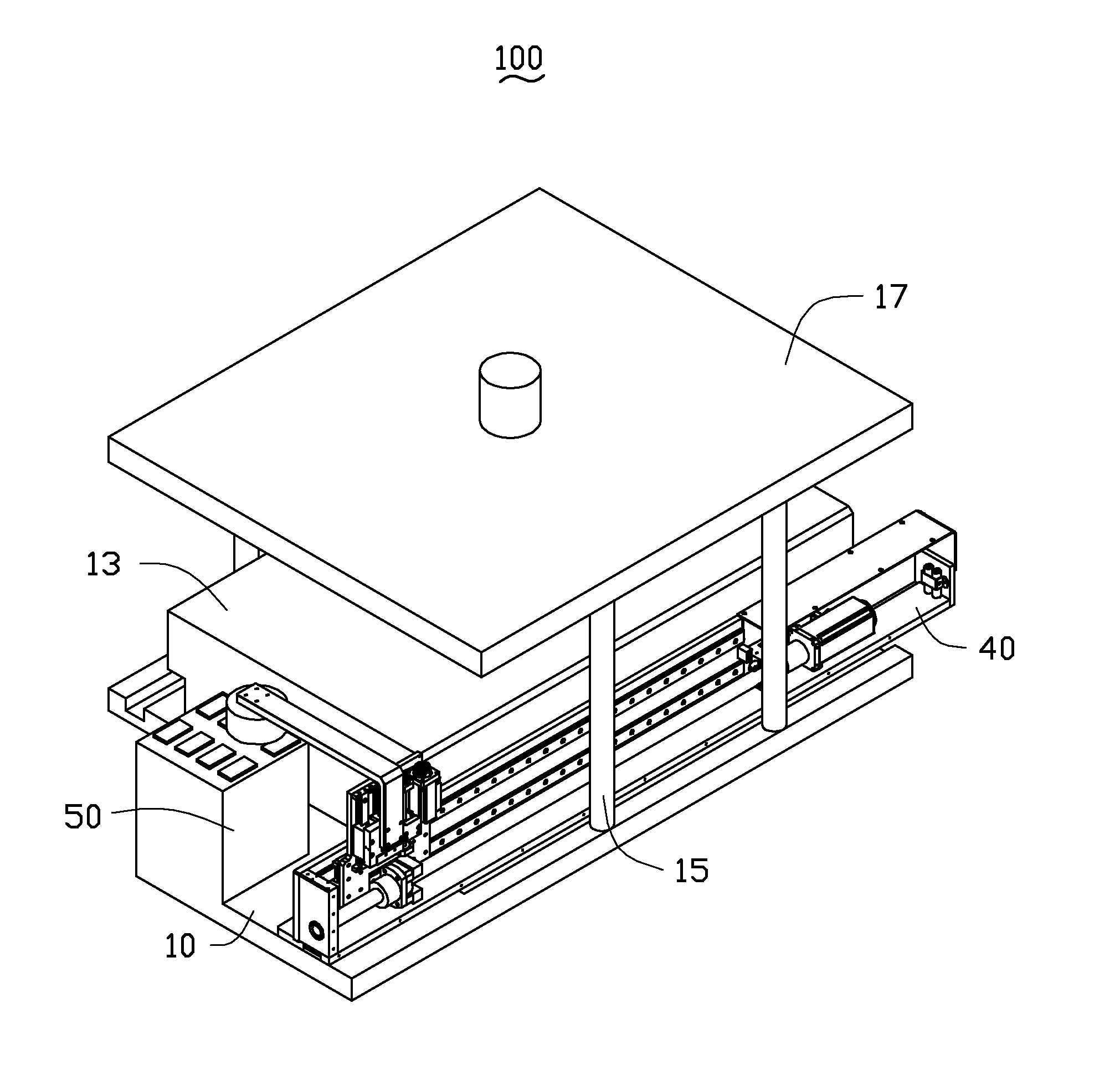
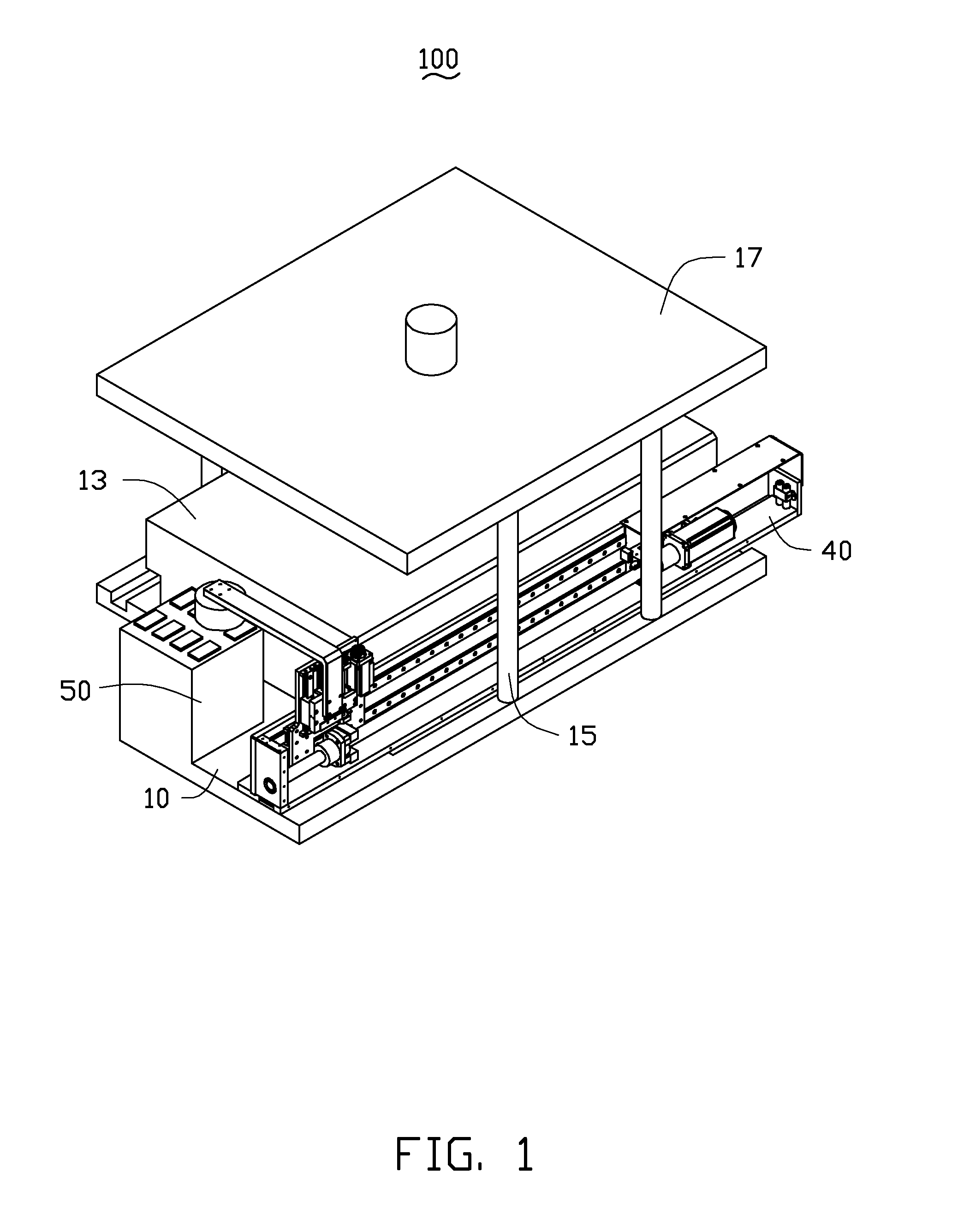
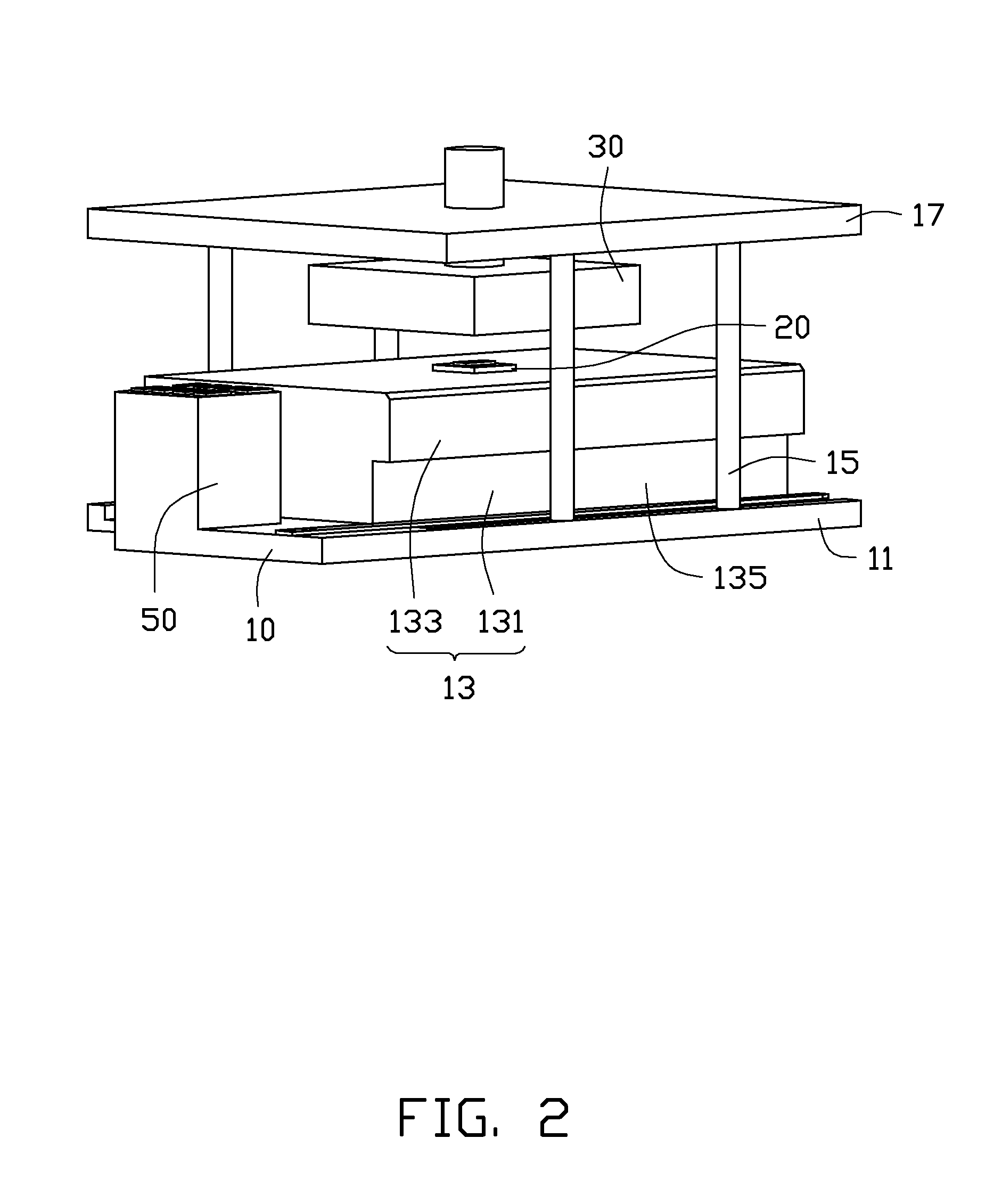
[0013]Referring to FIGS. 1 and 2, an embodiment of a punching machine 100 includes a base seat 10, a lower mold 20, an upper mold 30, a driver (not shown), a handling mechanism 40, and a workpiece feeding table 50. The lower mold 20 and the handling mechanism 40 are fixed on the base seat 10 and positioned adjacent to each other. The handling mechanism 40 clamps a workpiece from the workpiece feeding table 50 and positions the workpiece on the lower mold 20. The upper mold 30 is movably mounted over the lower mold 20 and connects with the driver. The upper mold 30 is driven by the driver and capable of punching the workpiece on the lower mold 20.

[0014]The base seat 10 includes a bottom plate 11, a support table 13, a plurality of support posts 15, and an upper plate 17. The bottom plate 11 is substantially a rectangular plate. The support table 13 is mounted on a middle portion of the bottom plate 11, and includes a support portion 131 and a bearing portion 133 connected to the supp...


PUM


Abstract

A handling mechanism to convey workpieces, includes a mounting seat, a first sliding member, a first driving assembly, a second sliding member, a second driving assembly, and a clamping assembly. The first sliding member is slidably mounted on the mounting seat. The first driving assembly is mounted on the mounting seat and capable of driving the first sliding member to slide along the longitudinal direction of the mounting seat. The second sliding member is slidably mounted on the first sliding member. The second driving assembly is mounted on the first sliding member and capable of driving the second sliding member to slide along a direction perpendicular to the longitudinal direction of the mounting seat. The clamping assembly is fixed to the second sliding member for clamping workpieces. The present invention further discloses a punching machine using the same.

Description

BACKGROUND[0001]1. Technical Field[0002]The present disclosure relates to handling mechanisms, and more particularly, to a handling mechanism used in a punching machine.[0003]2. Description of Related Art[0004]A conventional punching machine employs a handling mechanism to convey workpieces. One conventional handling mechanism includes a mounting seat, a driving assembly mounted on the mounting seat, and a sliding member driven by the driving assembly. However, the sliding member is merely capable of sliding relative to the mounting seat along one direction. In order to convey workpieces along two perpendicular directions, a robot has to be employed to work with the punching machine. However, the robot has a complicated structure, and the cost of the robot is relatively high.[0005]Therefore, there is room for improvement in the art.BRIEF DESCRIPTION OF THE DRAWINGS[0006]The components in the drawings are not necessarily drawn to scale, the emphasis instead placed upon clearly illust...

Claims


Application Information

Patent Timeline
IPC IPC(8): B25J11/00B21D43/00
CPCB21D43/02
Inventor CHEN, WEN-SHENGXU, ZHEN-HUA
Owner SHENZHENSHI YUZHAN PRECISION TECH CO LTD
Why Eureka
Try Eureka