Eureka AIR delivers breakthrough ideas for toughest innovation challenges, trusted by R&D personnel around the world.

Method for operating a converter and a switching cell and a converter

Active Publication Date: 2013-05-23
HITACHI ENERGY SWITZERLAND AG
View PDF3 Cites 19 Cited by
  • Summary
  • Abstract
  • Description
  • Claims
  • Application Information

AI Technical Summary

Benefits of technology

This patent describes a method and apparatus for operating a converter with multiple bridge branches and switching cells. When a fault is detected in a switching cell, the monitoring unit sends an indication to a central monitoring device, which can trigger a relevant triggering element to short-circuit the switching cell connections if there is no communication of a fault in a second switching cell within a predetermined period of time. This allows for faster fault detection and timely maintenance of the converter. The technical effect of this patent is to improve the reliability and efficiency of converters.

Problems solved by technology

So that the switching cell can quickly react to an identified fault, the individual switching cells may be provided with bridging elements, with the result that faulty switching cells can be reliably short-circuited.
However, many proposed bridging elements may only be short-circuited once and can no longer be readily opened.
Overcurrents in IGBTs, which result in desaturation, can now be caused not only by faults in the switching cells themselves but also by other faults which occur outside the power converter or outside the switching cells.
However, since faults which are outside the relevant switching cell are also incorrectly associated with a switching cell with the structure described above, the situation may arise in which functional switching cells are bridged and, as a result, would be rendered permanently non-functional since the short circuit across the switching cell cannot be canceled again using a simple measure.
However, it has hitherto been assumed that each switching cell in which a fault is identified is defective or faults in the switching cells are identified outside the switching cells and are associated with the switching cells by complicated analysis methods.

Method used


Image

  • Method for operating a converter and a switching cell and a converter
  • Method for operating a converter and a switching cell and a converter
  • Method for operating a converter and a switching cell and a converter

Examples


Embodiment Construction

[0022]Exemplary embodiments of the present disclosure provide that, in a modular direct converter having switching cells, none of the switching cells is permanently short-circuited on account of an incorrectly identified fault inside the switching cell.

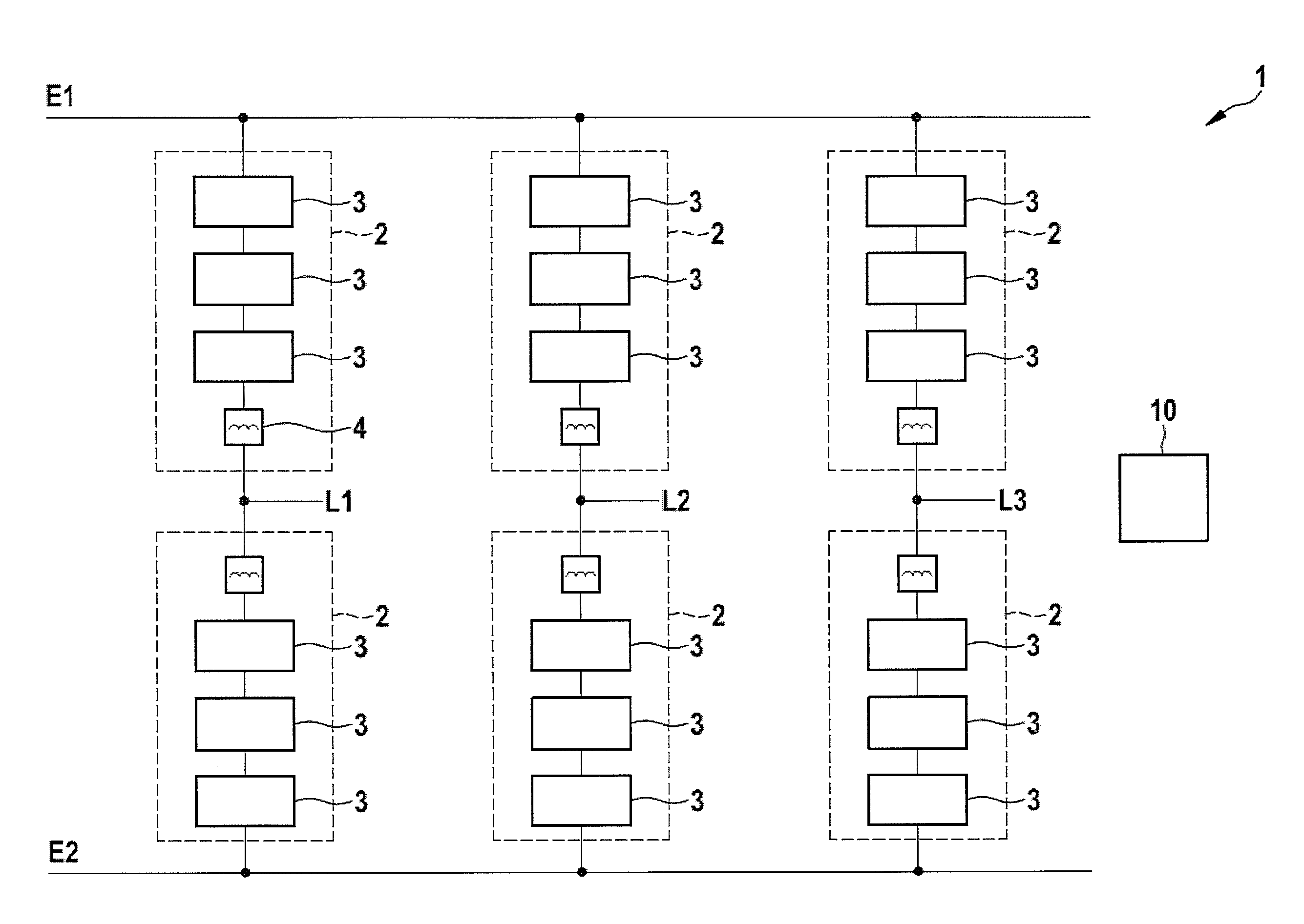
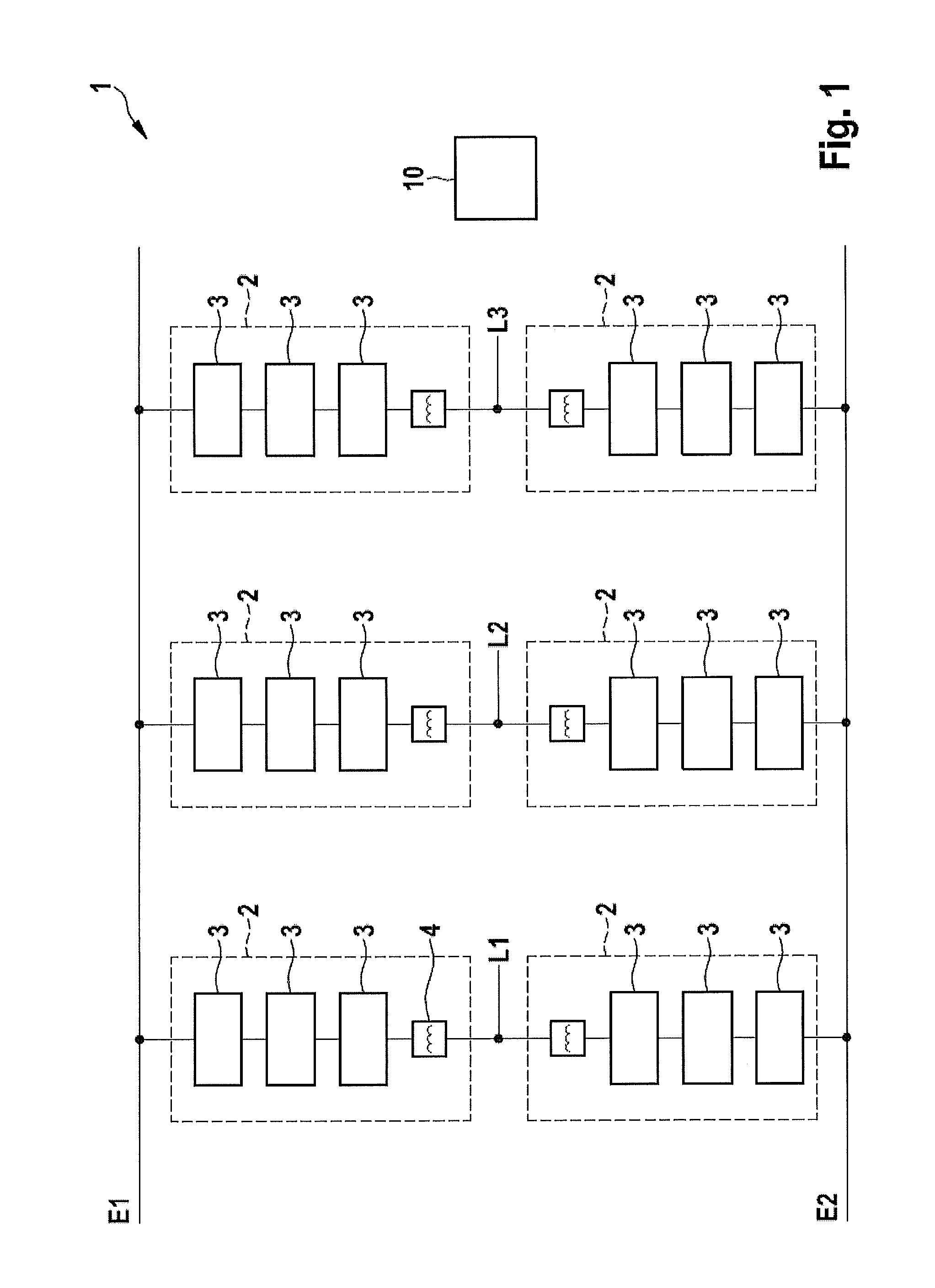
[0023]An exemplary embodiment disclosed herein provides a method for operating a converter, wherein the converter includes a plurality of bridge branches having one or more switching cells connected in series, wherein each bridge branch connects one of a plurality of inputs to one of a plurality of outputs of the converter,

[0024]The method includes steps in which each of the switching cells is monitored in order to determine a fault, if a fault is identified in one of the switching cells, one of the triggering elements for short-circuiting switching cell connections is triggered if the fault identified in the switching cell is not followed by identification of a fault in a further one of the switching cells, wherein the identification...


PUM


Abstract

Exemplary embodiments are directed to a method for operating a converter, wherein the converter includes a plurality of bridge branches having one or more switching cells connected in series. Each bridge branch connects one of a plurality of inputs to one of a plurality of outputs of the converter. The method includes monitoring each of the switching cells in order to determine a fault. If a fault is identified in one of the switching cells, triggering one of the triggering elements for short-circuiting switching cell connections if the fault identified in the switching cell is not followed by identification of a fault in a further one of the switching cells within a predetermined period of time.

Description

RELATED APPLICATION[0001]This application claims priority under 35 U.S.C. §119 to European application 11190134.4 filed in Europe on Nov. 22, 2011, the content of which is hereby incorporated by reference in its entirety.FIELD[0002]The disclosure relates to converters, such as modular multi-level power converters, and measures for identifying faults in a converter.BACKGROUND INFORMATION[0003]Known converter circuits are used in various ways. For example, direct converters have advantages for operating drives since in some implementations they can drive higher currents than indirect converters with the same effort.[0004]Modular multi-level converters (abbreviations=MMC, MMLC or M2LC) are used, for example, as direct converters. Such converters have converter branches which connect each input-side phase line to an output-side phase line. Such converters may also be used as partial converters which are connected to one another in series.[0005]Each of the converter branches has a series...

Claims


Application Information

Patent Timeline
IPC IPC(8): H02H7/10
CPCH02H7/10H02M1/32H02H7/12H02M2001/325H02M2007/4835H02M7/49H02M1/325H02M7/4835
Inventor KORN, ARTHUR
Owner HITACHI ENERGY SWITZERLAND AG
Why Eureka
Eureka Blog
Learn More