Wireless power

Active Publication Date: 2013-06-06
CHINTALA SANDEEP KUMAR
View PDF19 Cites 12 Cited by
  • Summary
  • Abstract
  • Description
  • Claims
  • Application Information

AI Technical Summary

Problems solved by technology

Wire and cable have the disadvantage of being lossy, particularly at higher frequencies, are not immune from crosstalk, and, due to inherent inter-conductor capacitance, can impose a maximum and relatively low bandwidth or data rate on any signal.
Another problem with wire or cable data transfer links is the existence of inherent characteristic impedance which has to be accurately matched by terminations if reflections in the wire of cable are to be avoided.
Reflections can destroy the intelligibility of digital signals and limit the useful distance a digital signal can be propagated.
Yet another disadvantage of wires and cables is the immovability of the equipment to which they are attached.
However, the cables are once again fixed, making movement of the equipment to

Method used


Image

  • Wireless power
  • Wireless power
  • Wireless power

Examples


Embodiment Construction

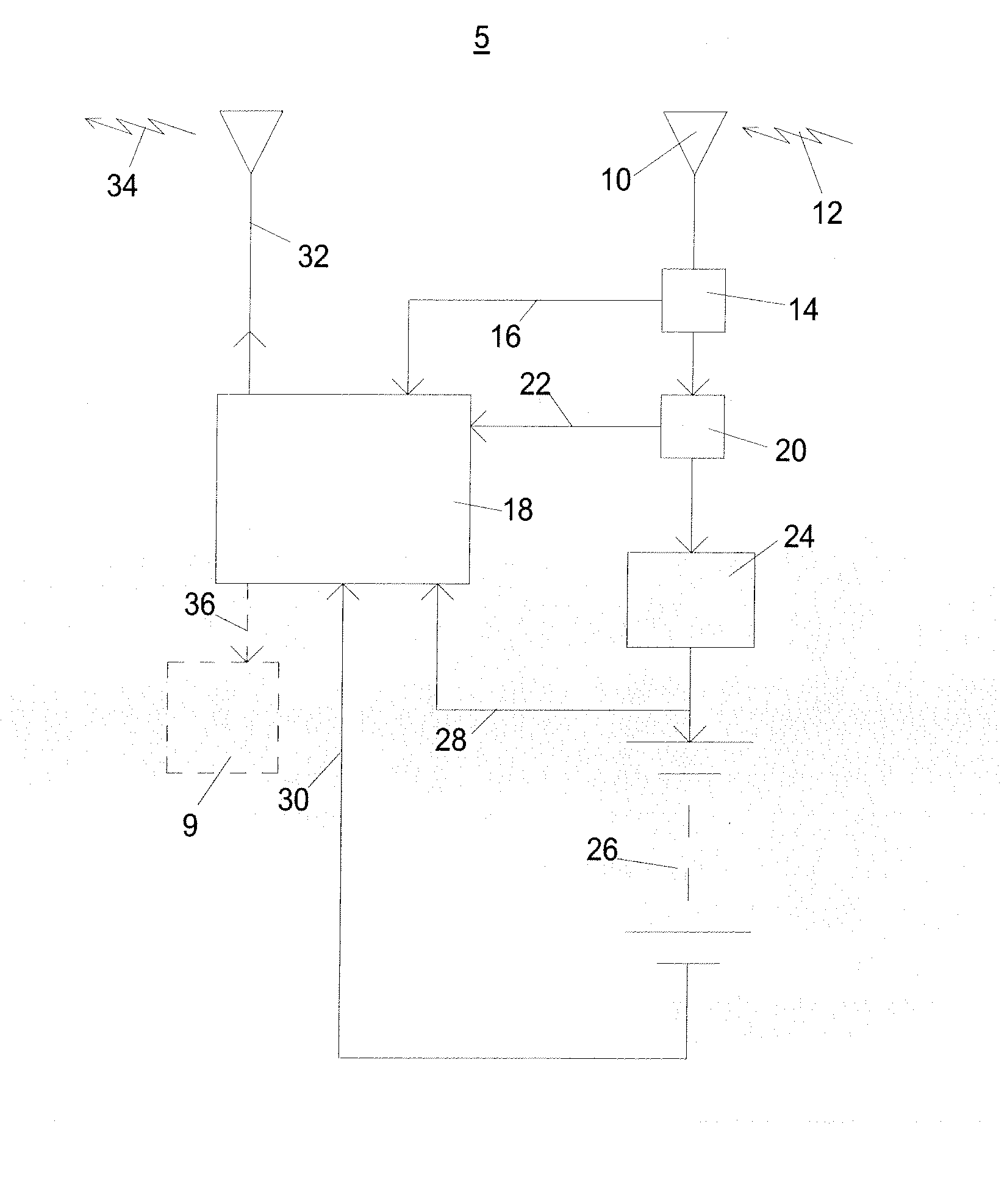
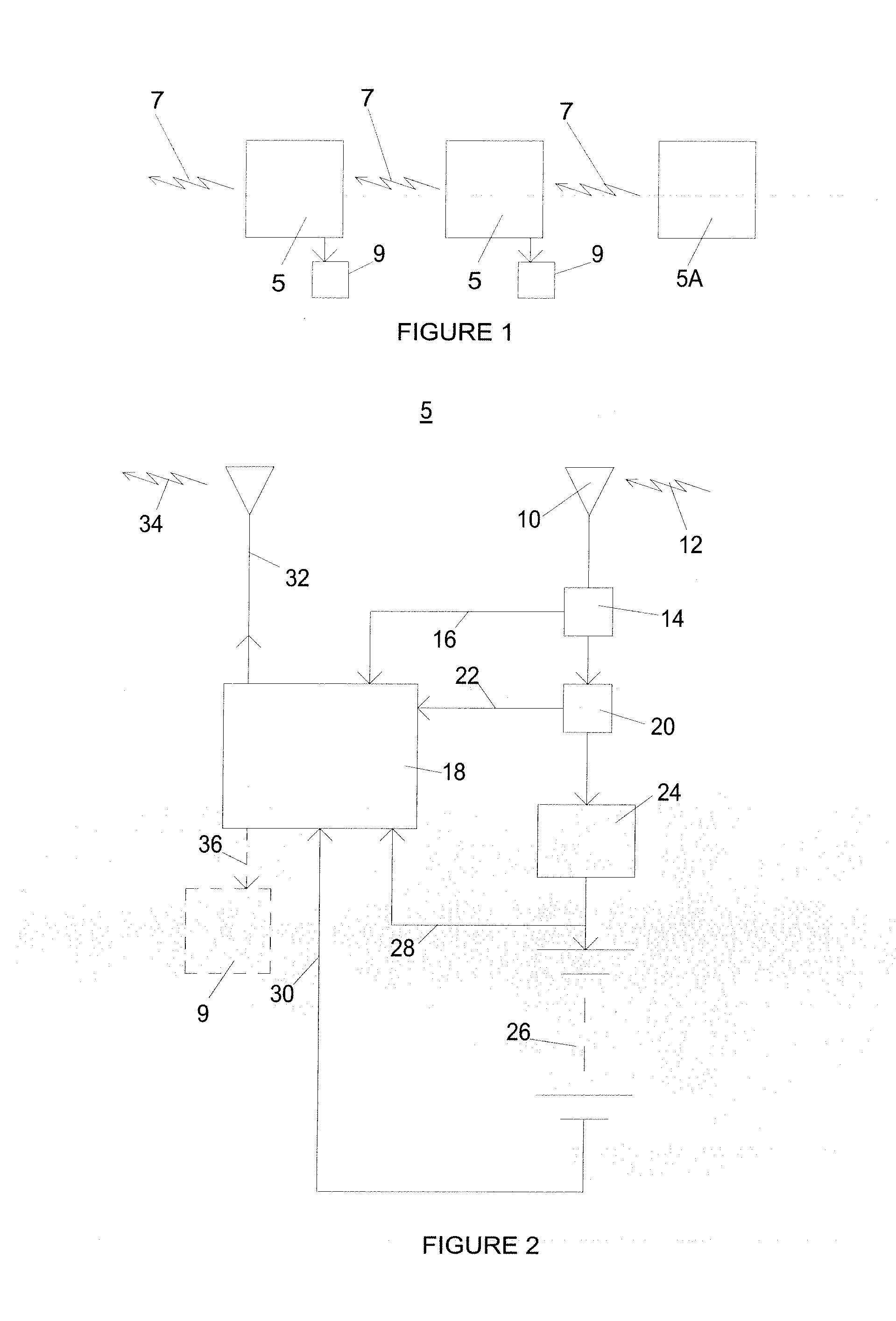
[0026]Attention is first to FIG. 1, showing a chain of data and energy transfer apparatus 5 coupled together by data signals 7, being radio or magnetic induction signals, or both, or mixed. Data receiving powered apparatus 9 can be coupled to some or all of the data and energy transfer apparatus 5 in the chain to receive power via the data signals. One data and energy transfer apparatus 5A is at the head of the chain, and does not need to receive an energizing data signal 7, but rather derives its energy from another power source such as a mains derived power supply, and its data signals from a data source (not shown).

[0027]So long as the cumulative energy loss between data and energy transfer apparatus 5 down the chain is insufficient to prevent the ability to of the penultimate data and energy transfer apparatus 5 in the chain to provide an outgoing data signal the final data and energy transfer apparatus 5 in the chain to power the data receiving powered apparatus 9, the chain wi...


PUM


Abstract

An apparatus can receive and transfer data and energy between adjacent apparatus in a chain. Each apparatus comprises an input antenna for receiving an input signal which is tuned and impedance matched for a receiver and demodulator in a control circuit. The demodulated signal is provided as input to a transmitter module to create an output signal. The input signal is then impedance transformed to generate a sufficient voltage to energize a power supply which charges a battery. The input signal and the output signal can be a radio signal, a magnetic induction signal, or a combined radio and magnetic induction signal. A controller in the control circuit monitors the condition of the battery and power supply and controls a switch operable to selectively power parts of the apparatus dependently upon their monitored condition.

Description

CROSS REFERENCE TO RELATED APPLICATIONS[0001]This patent application is a national phase entry under 35 U.S.C. §371 of PCT International Patent Application PCT / EP2011 / 064002, filed Aug. 13, 2011, designating the United States and published in English as international Patent Publication WO2012 / 069218 A1 on May 31, 2012, which claims the benefit, under Article 8 of the PCT, of U.K. Patent Application No. GB 1013590.3, filed Aug. 13, 2010, the entire disclosure of each of which is hereby incorporated herein by this reference.FIELD OF THE INVENTION[0002]The present invention relates to data wireless transfer between equipment. It further relates to data transfer where the total energy required is minimized.BACKGROUND OF THE INVENTION[0003]Digital data is now commonly transferred within buildings and dwellings. A non exhaustive list, to which many others could be added, includes instructional and informational digital signals provided between items of computer equipment, control and feed...

Claims


Application Information

Patent Timeline
IPC IPC(8): H02J17/00
CPCH02J17/00H02J5/005H02J7/025H02J50/80H02J50/12H04B5/0037H04B5/0075H02J50/23H03H7/38
Inventor CHINTALA, SANDEEP KUMAR
Owner CHINTALA SANDEEP KUMAR
Why Eureka
Try Eureka