Method for equivalently connecting subassemblies in 1:N redundancy

a technology of standby circuit and subassembly, applied in the field of standby circuit implementation of assemblies in 1 : n redundancy, can solve the problems of configuration running counter, loss of system dynamics, loss of more valuable time, etc., and achieve the effect of faster and more efficien

Inactive Publication Date: 2005-04-19
NOKIA SIEMENS NETWORKS GMBH & CO KG
View PDF13 Cites 0 Cited by
  • Summary
  • Abstract
  • Description
  • Claims
  • Application Information

AI Technical Summary

Benefits of technology

[0012]The invention is based on the object of providing a way of implementing standby circuit...

Problems solved by technology

However, the higher-ranking mechanism MPSA is mainly occupied with standby circuiting measures, which results in a loss of system dynamics.
Further, a number of other assemblies that actually do not participate in the switchover process itse...

Method used


Image

  • Method for equivalently connecting subassemblies in 1:N redundancy
  • Method for equivalently connecting subassemblies in 1:N redundancy

Examples


Embodiment Construction

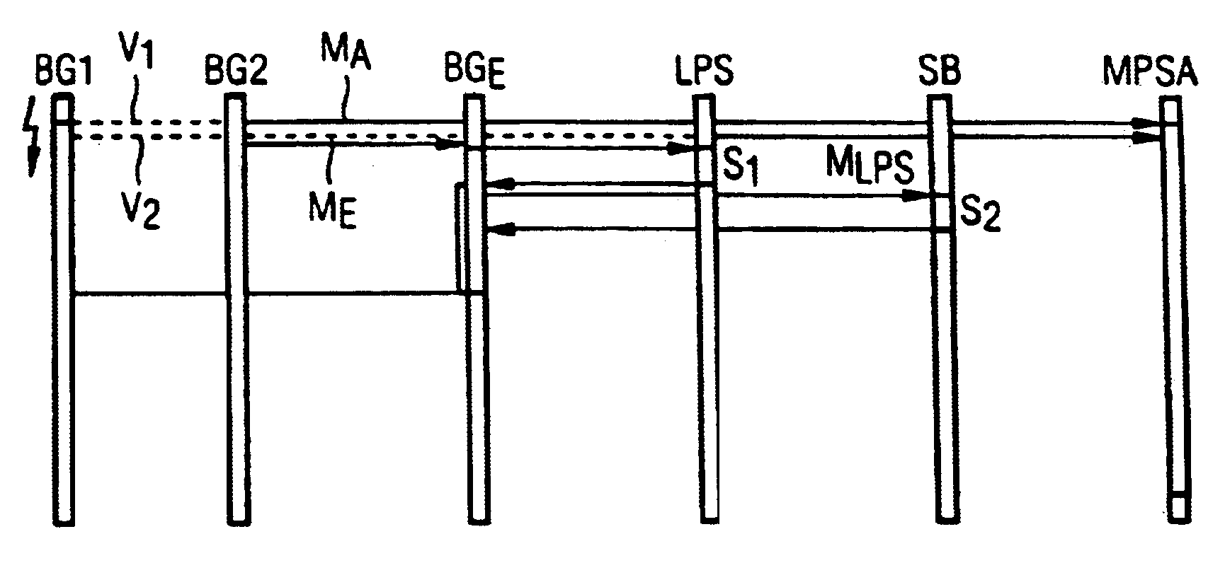
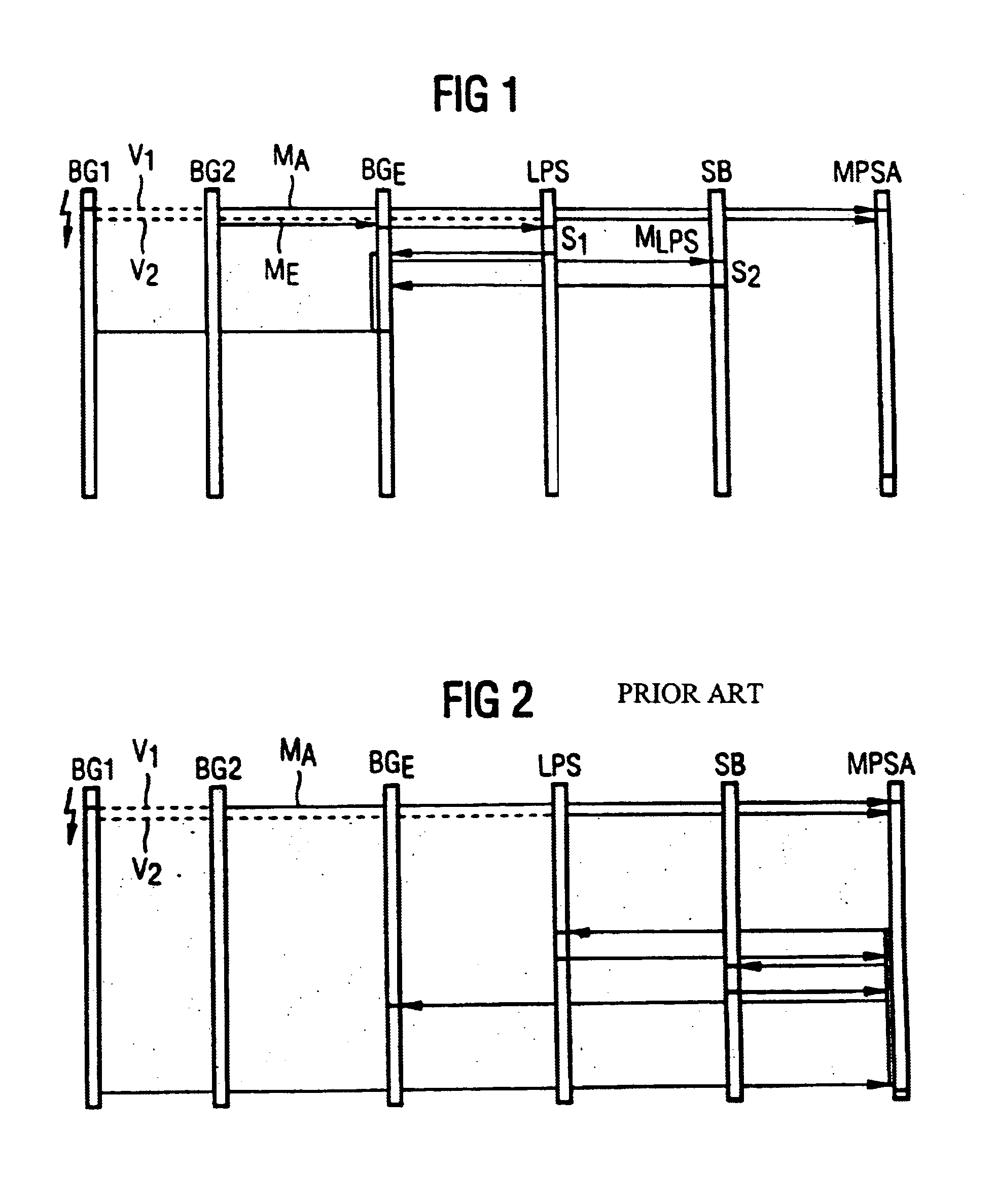
[0020]FIG. 1 shows a configuration on which the inventive method is run in which peripheral line assemblies BG1 . . . BGn are provided, (only two of these peripheral line assemblies BG1, BG2 are shown). The two assemblies are respectively allocated to one another in pairs and comprise connections V1 to one another via which a mutual monitoring is carried out. Further, internal and external interfaces are allocated to the peripheral line assemblies BG1 . . . BGn. The internal interfaces serve as interfaces the assemblies AMX of the ATM switching network, whereas the external interfaces represent interfaces to the connected trunks hereto for the other switching network devices. The assemblies BG1 . . . BG2 also comprise connections V2 to the assemblies AMX of the ATM switching network, (only the connection V2 of the assemblies BG1 to the assemblies AMX is shown here). All assemblies BG1 . . . BGn as well as the allocated internal and external interfaces are monitored and controlled by...


PUM


Abstract

In the Prior Art, a higher-ranking mechanism controls the standby circuiting of assemblies in 1:N redundancy, resulting in a system dynamics loss. The invention solves this problem in that the devices responsible for the standby circuiting events in the higher-ranking mechanism are relocated into a standby circuit assembly of the 1:N redundancy provided for standby circuiting purposes. The standby circuit events are thus controlled and monitored by the standby circuit assembly itself, relieving the higher-ranking mechanism of these tasks.

Description

BACKGROUND OF THE INVENTION[0001]1. Field of the Invention[0002]The invention is directed to a method for implementing standby circuiting of assemblies in 1:N redundancy.[0003]2. Description of the Related Art[0004]Redundancies are often used to improve reliability in communication systems. Depending on the required reliability of a communication means, different redundancy structures can be provided for the associated peripheral line assemblies. Examples of this are the “1+1” or the “1:N” line assembly redundancy described in “IEEE Journal on Selected Areas in Communications”, Vol. 15, No. 5, June 1997, pages 795 through 806. For a “1+1′ redundancy structure, two line assemblies are operated parallel in order to redundantly transmit message signal streams over them, only one of these redundant message signal streams is considered for the further-processing.[0005]For a “1:N” line assembly redundancy, a single standby line assembly or standby circuit assembly is provided in addition ...

Claims


Application Information

Patent Timeline
IPC IPC(8): H04Q3/64
CPCH04Q3/64H04Q2213/1302H04Q2213/1334H04Q2213/13166H04Q2213/13167H04Q2213/1304
Inventor KOPP, JORGHUBER, SIEGFRIEDHOFFMANN, GERTRODER, ANNETTE
Owner NOKIA SIEMENS NETWORKS GMBH & CO KG
Why Eureka
Try Eureka