
Support mechanism

a technology of supporting mechanism and support rod, which is applied in the direction of electrolysis process, electrolysis components, etc., can solve the problems of limited supply to the workpiece mounted on the fixture, limiting the polishing efficiency,

Inactive Publication Date: 2013-09-05
ANHUI HONGQING PRECISION MACHINE
View PDF2 Cites 0 Cited by
  • Summary
  • Abstract
  • Description
  • Claims
  • Application Information

AI Technical Summary

Benefits of technology

The present patent is about a support mechanism used in an electro plasma polishing process. The technical effect of the patent is to improve the polishing efficiency by providing a support mechanism that can supply power to the workpiece more effectively. The support mechanism includes a support beam, multiple electrically conducting assemblies, and positioning assemblies, which are mounted on the support beam and connected to external anodes. This allows for a more even distribution of power and improved polishing efficiency.

Problems solved by technology

However, since the support mechanism is electrically connected to a single anode, the power supplied to the workpiece mounted on the fixture is limited, thereby limiting the polishing efficiency.

Method used


Image

  • Support mechanism
  • Support mechanism
  • Support mechanism

Examples


first embodiment

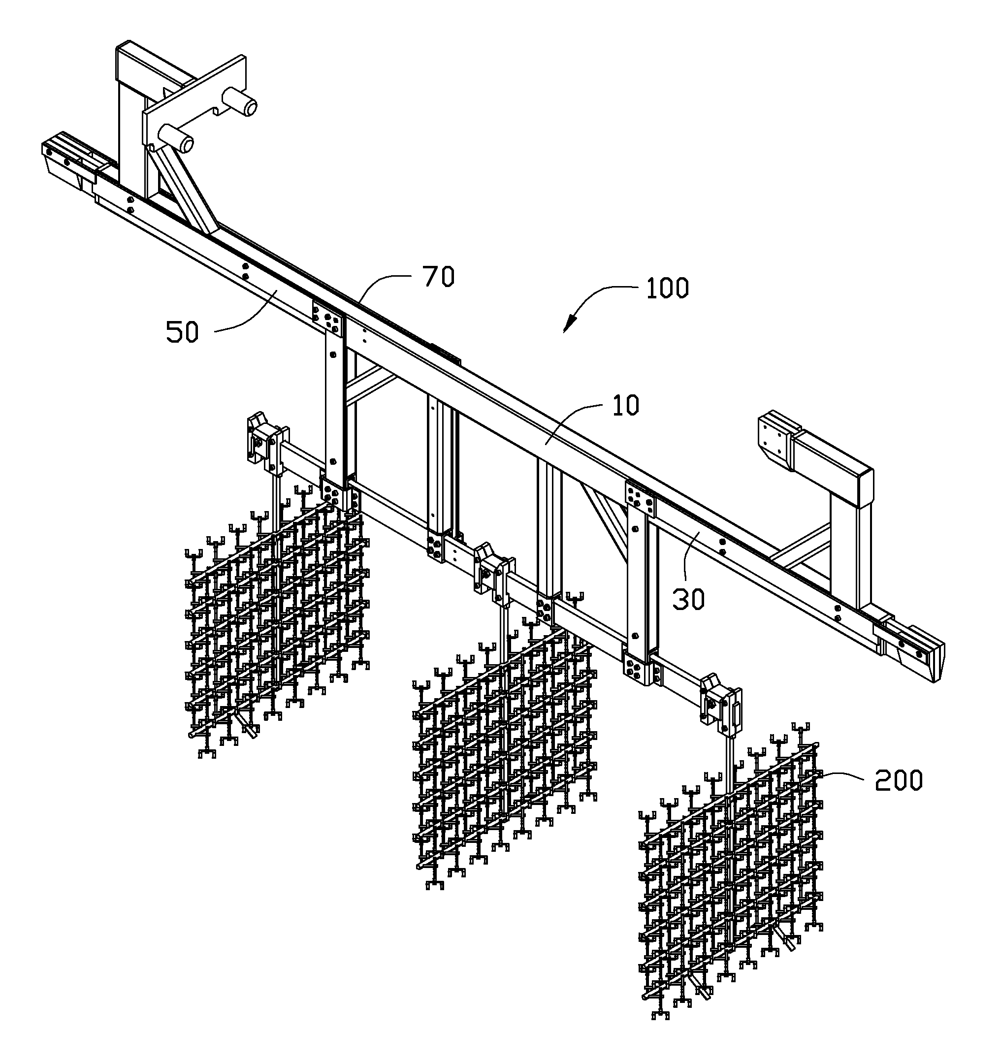
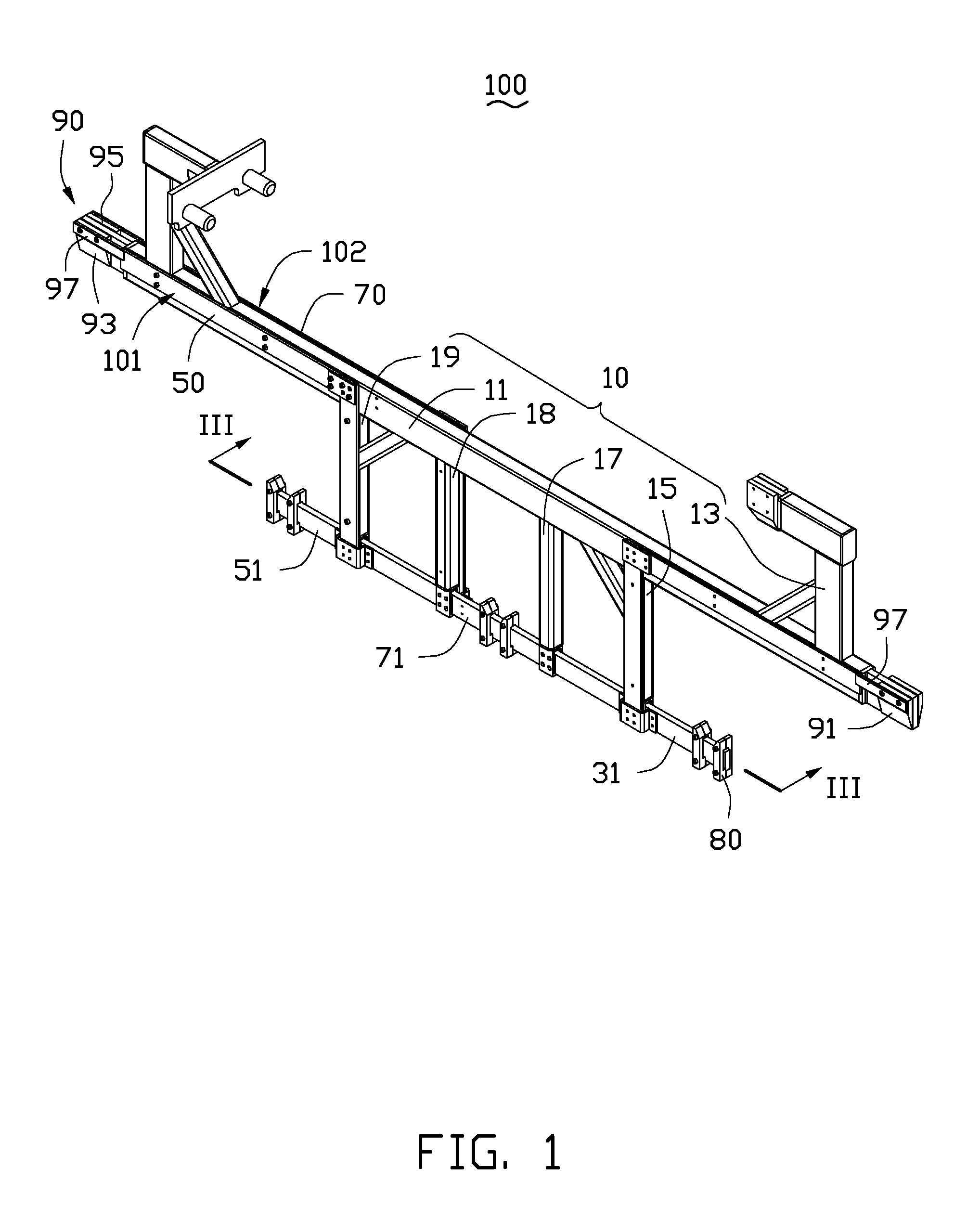
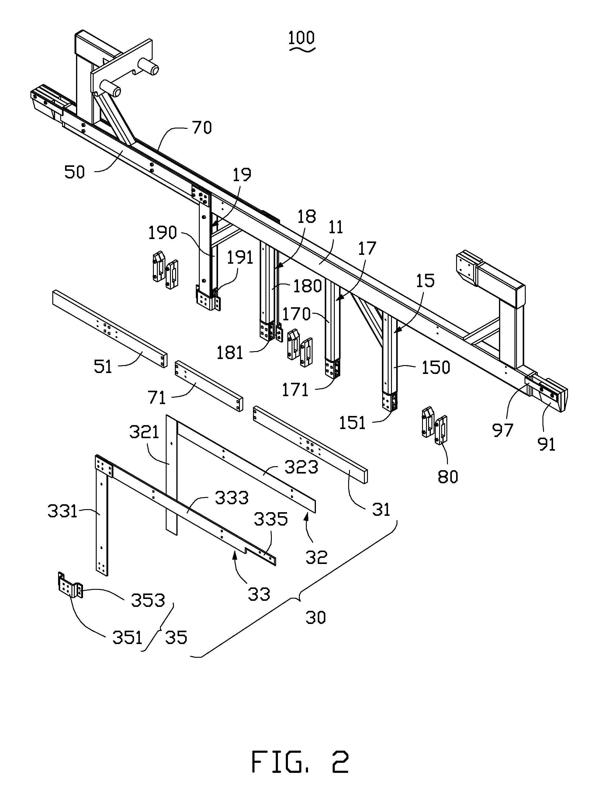
[0014]FIGS. 1 through 6 show a support mechanism 100 of a first embodiment for supporting a plurality of fixtures 200 during an electro plasma polishing process. The support mechanism 100 includes a support beam 10, a first electrically conducting assembly 30, a second electrically conducting assembly 50, a third electrically conducting assembly 70, a plurality of positioning assemblies 80, and a connection assembly 90. The first electrically conducting assembly 30, the second electrically conducting assembly 50, and the third electrically conducting assembly 70 are mounted on the support beam 10, and are electrically connected to three different external anodes (not shown) by the connection assembly 90.

[0015]Referring also to FIGS. 2 and 6, the first electrically conducting assembly 30 and the second electrically conducting assembly 50 are separately mounted on one side of the support beam 10. The third electrically conducting assembly 70 is mounted on an opposite side of the suppo...

second embodiment

[0028]FIG. 7 shows a support mechanism 300 of a second embodiment for supporting a plurality of fixtures 200 during an electro plasma polishing process. The support mechanism 300 has a structure similar to the support mechanism 100. However, a support beam 310 of the support mechanism 300 includes a first support portion 3101, a second support portion 3103, and an electrically insulating connecting member 3105 connecting the first support portion 3101 to the second support portion 3103. The support mechanism 300 includes a first electrically conducting assembly 330 and a second electrically conducting assembly 350. The first electrically conducting assembly 330 is mounted on the first support portion 3101, and the second electrically conducting assembly 350 is mounted on the second support portion 3103. A first bearing pole 3301 of the first electrically conducting assembly 330 and a second bearing pole 3501 of the second electrically conducting assembly 350 are connected by an elec...


PUM

PropertyMeasurementUnit
Electrical conductoraaaaaaaaaa
aaaaaaaaaa

Abstract

A support mechanism used in an electro plasma polishing process includes a support beam, a first electrically conducting assembly, and a second electrically conducting assembly. The first electrically conducting assembly and the second electrically conducting assembly are mounted on the support beam. The first electrically conducting assembly is electrically insulated from the second electrically conducting assembly.

Description

BACKGROUND[0001]1. Technical Field[0002]The present disclosure relates to support mechanisms, and particularly to a support mechanism used in an electro plasma polishing process.[0003]2. Description of Related Art[0004]In an electro plasma polishing process, a plurality of workpieces is fixed on a fixture, the fixture with the workpieces is then mounted on a support mechanism. The support mechanism is electrically connected to an anode, and then is mounted on a lifting device. The workpiece mounted on the fixture is immersed in an electrolyte solution and electrically connected to a cathode and polished. However, since the support mechanism is electrically connected to a single anode, the power supplied to the workpiece mounted on the fixture is limited, thereby limiting the polishing efficiency.[0005]Therefore, there is room for improvement in the art.BRIEF DESCRIPTION OF THE DRAWINGS[0006]The components in the drawings are not necessarily drawn to scale, the emphasis instead place...

Claims


Application Information

Patent Timeline
IPC IPC(8): C25F7/00C25F3/16
CPCC25F3/16C25F7/00
Inventor HUANG, TIAN-FENGLI, BOWANG, WEN-LILEE, HAO-CHUNG
Owner ANHUI HONGQING PRECISION MACHINE
Learn More