Electrical system enclosures

a technology of electrical system and enclosure, applied in the field of enclosure, can solve problems such as problems such as the problem of transporting such enclosures

Inactive Publication Date: 2013-10-03
GENERAL ELECTRIC CO
View PDF0 Cites 11 Cited by
  • Summary
  • Abstract
  • Description
  • Claims
  • Application Information

AI Technical Summary

Problems solved by technology

However, it should be appreciated that as electrical system enclosures are generally

Method used


Image

  • Electrical system enclosures
  • Electrical system enclosures
  • Electrical system enclosures

Examples


Embodiment Construction

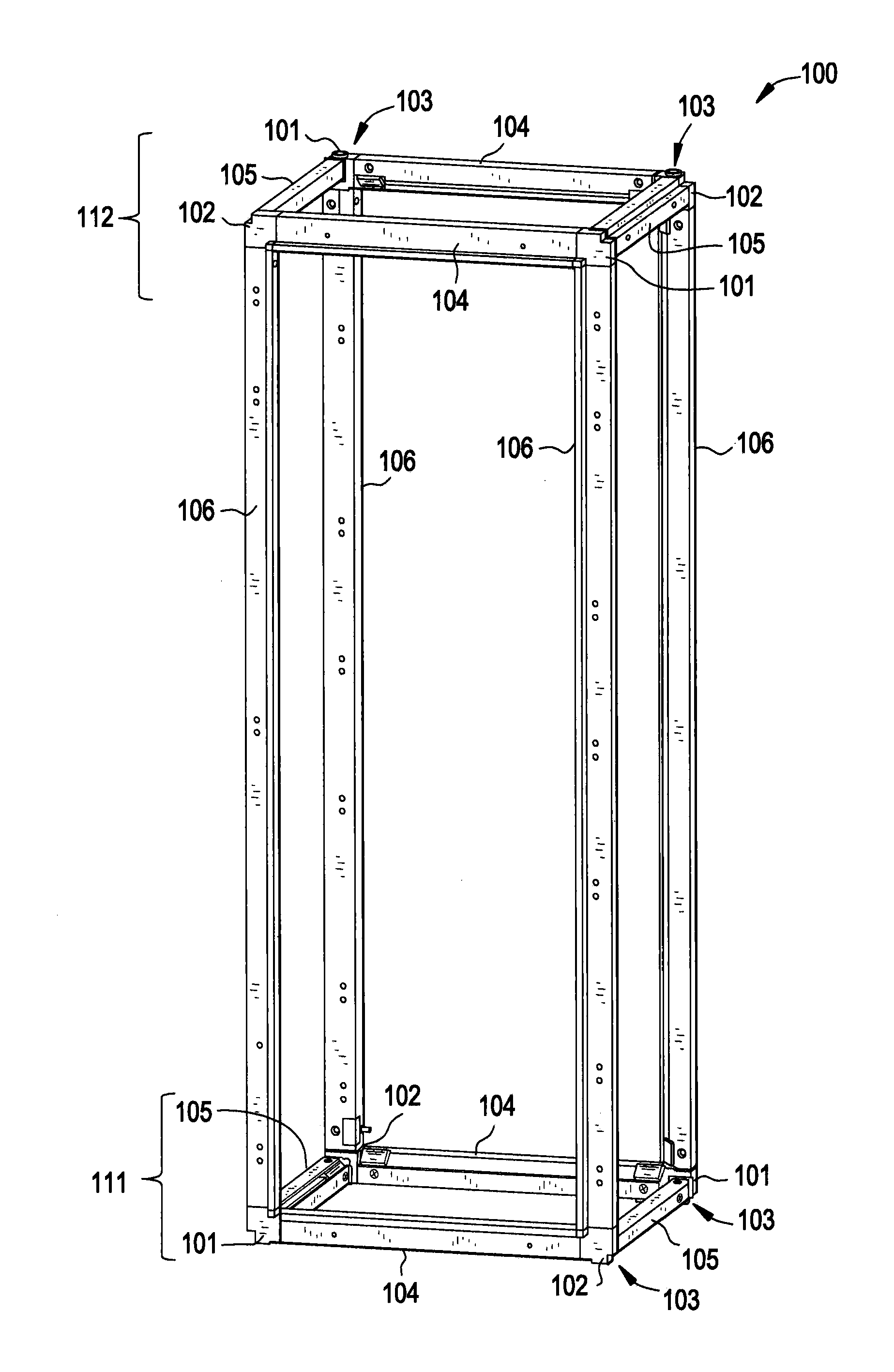
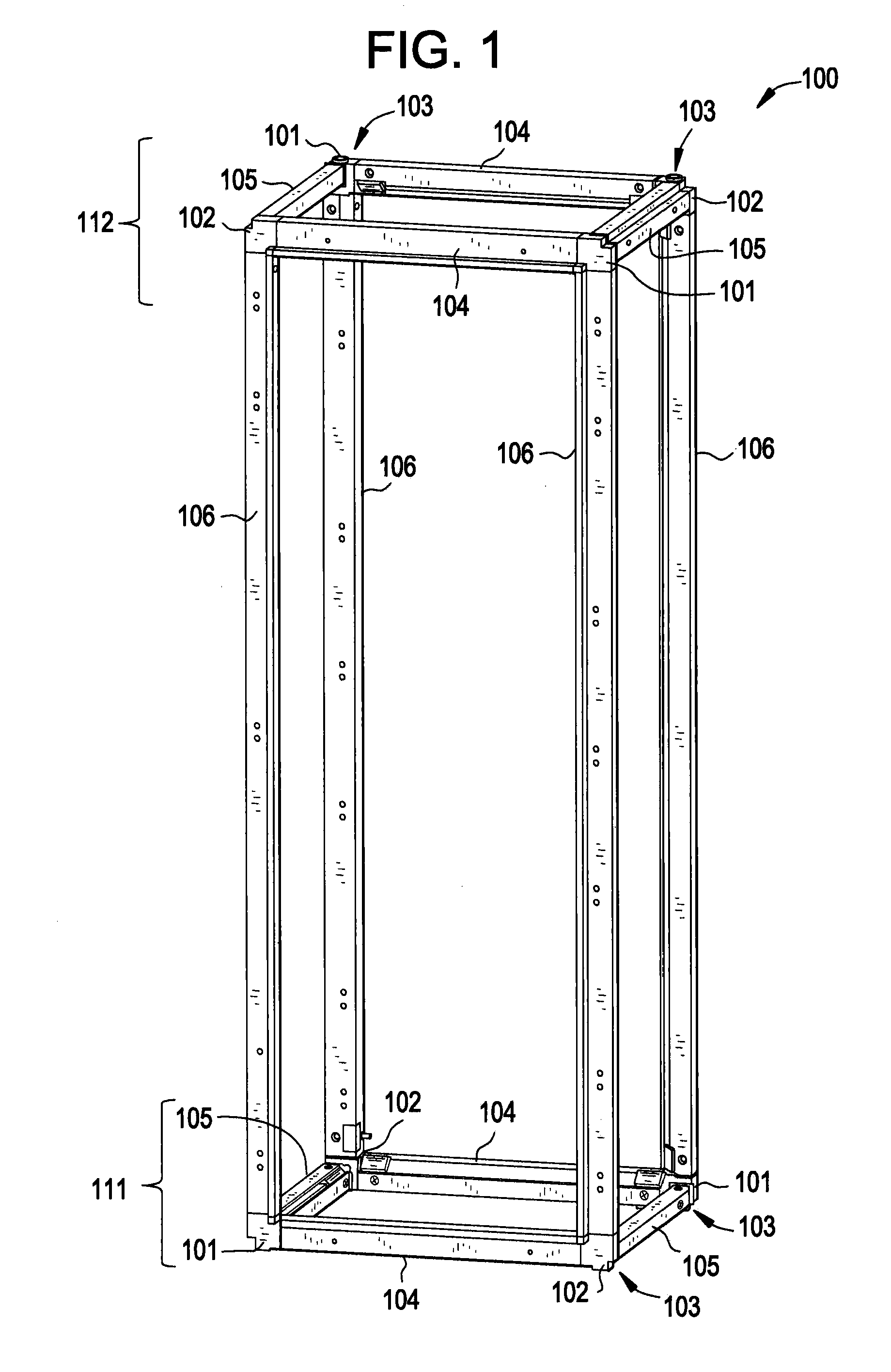
[0043]As described above, conventional electrical system enclosures may be problematic in that transportation is cumbersome due to the conventional, fully-assembled welded manner of assembly. However, exemplary embodiments of the present invention provide a solution which significantly reduces a volume required for transport while maintaining an appropriate level of ingress protection as compared to conventional welded enclosures.

[0044]Turning to FIG. 1, a perspective view of a supportive frame of an electrical system enclosure is provided. As illustrated, the frame 100 includes four corner support structures 101 (e.g., a first set of corner support structures), four corner support structures 102 (e.g., a second set of corner support structures), eight gasket assemblies 103, four horizontal framing support members 104, four horizontal framing support members 105, and four vertical framing support members 106. As shown, the corner support structures 101 and 102 engage proximate frami...


PUM


Abstract

A frame for an enclosure includes a first set of corner support structures. Each corner support structure of the first set of corner support structures includes a main body, a first protrusion arranged to extend from the main body, a second protrusion arranged to extend from the main body and substantially orthogonal to the first protrusion, and a third protrusion arranged to extend from the main body and substantially orthogonal to both the first protrusion and the second protrusion. The frame further includes a second set of corner support structures having mirror image symmetry about a plane of symmetry of an opposing corner support structure of the first set of corner support structures.

Description

BACKGROUND OF THE INVENTION[0001]The subject matter disclosed herein relates to an enclosure, more particularly to electrical system enclosures, and even more particularly, exemplary embodiments of the present invention are directed to collapsible and easily transportable frames for electrical system enclosures.[0002]Some electrical system enclosures comprise a stiff, welded unibody construction or a welded frame construction. The welds ensure a particular level of ingress protection which ensures dust, water vapor, and other substances cannot intrude within supportive framing of the enclosures. However, it should be appreciated that as electrical system enclosures are generally of a substantial size, the transportation of such welded enclosures is problematic.BRIEF DESCRIPTION OF THE INVENTION[0003]According to an exemplary embodiment of the present invention, a frame for an enclosure includes a first set of corner support structures and a second set of corner support structures, w...

Claims


Application Information

Patent Timeline
IPC IPC(8): A47F5/14
CPCH02B1/014
Inventor OBOZA, RAFAL MARCINBEDKOWSKI, JOZEF ZBIGNIEWBURZYNSKI, RAFAL MICHALDE CUYPER, JOHAN RENE SYLVAINKOWALSKI, PAWEL PIOTRSEKULA, MATEUSZ BARTLOMIEJTOMANEK, TOMASZ PAWEL
Owner GENERAL ELECTRIC CO
Why Eureka
Try Eureka