Wireless communication between tools

Inactive Publication Date: 2013-10-03
WELLTEC AS
4 Cites 14 Cited by

AI-Extracted Technical Summary

Problems solved by technology

However, well fluid is most often very inhomogeneous as it comprises mud, scales, both oil and water, and gas bubbles.
However, when this is the case, communication between the tools of the other operator is hindered as these tools are separated by the...

Benefits of technology

[0005]It is an object of the present invention to wholly or partly overcome the above disadvantages and drawbacks of the prior art. More specifi...

Abstract

The present invention relates to a downhole tool system for being submerged into a casing, comprising at least three tools having a tool axis. Furthermore, the present invention relates to a downhole tool system for being submerged into a casing, comprising at least three tools, and finally the invention relates to communication methods for communicating wirelessly between a first and a third tool separated by a second tool.

Application Domain

SurveyConstructions +2

Technology Topic

Engineering

Image

  • Wireless communication between tools
  • Wireless communication between tools
  • Wireless communication between tools

Examples

  • Experimental program(1)

Example

[0058]All the figures are highly schematic and not necessarily to scale, and they show only those parts which are necessary in order to elucidate the invention, other parts being omitted or merely suggested.
DETAILED DESCRIPTION OF THE INVENTION
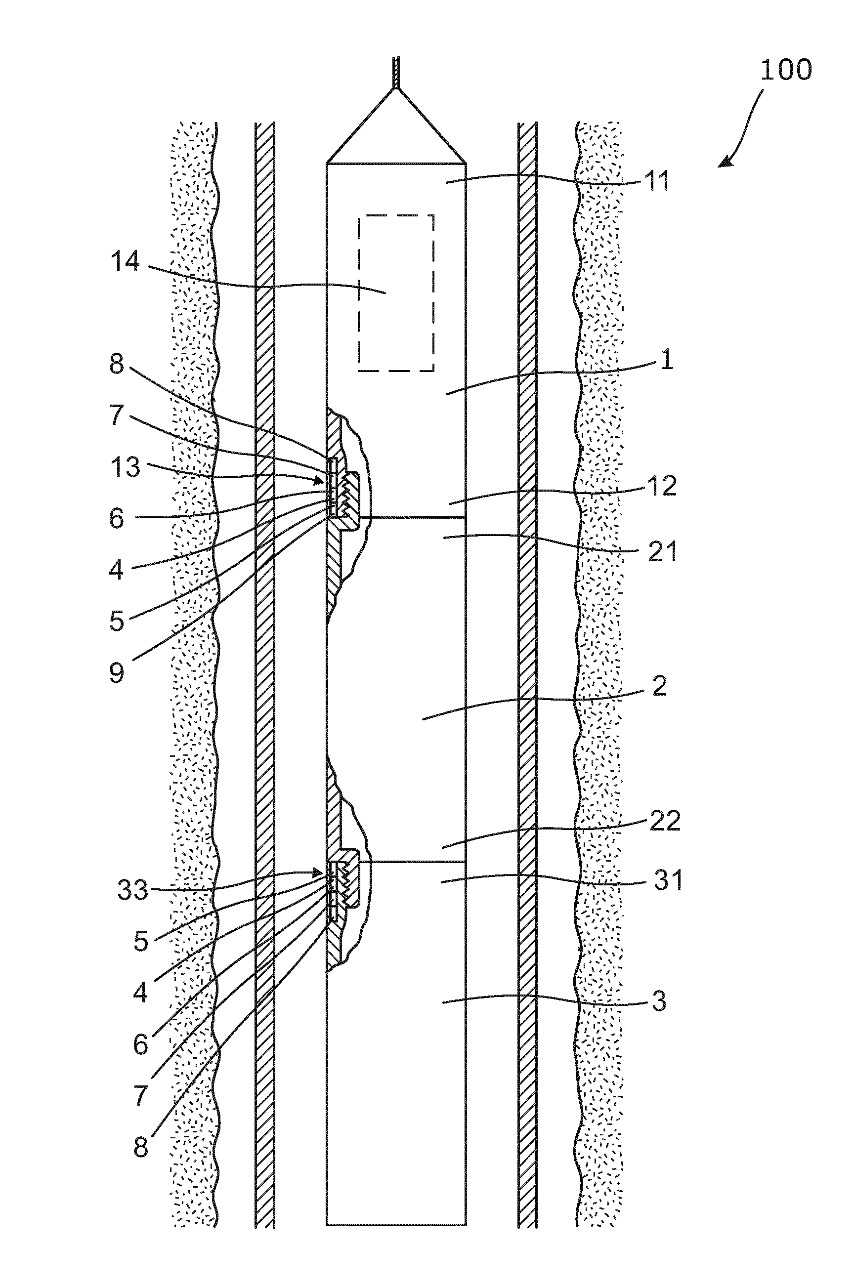
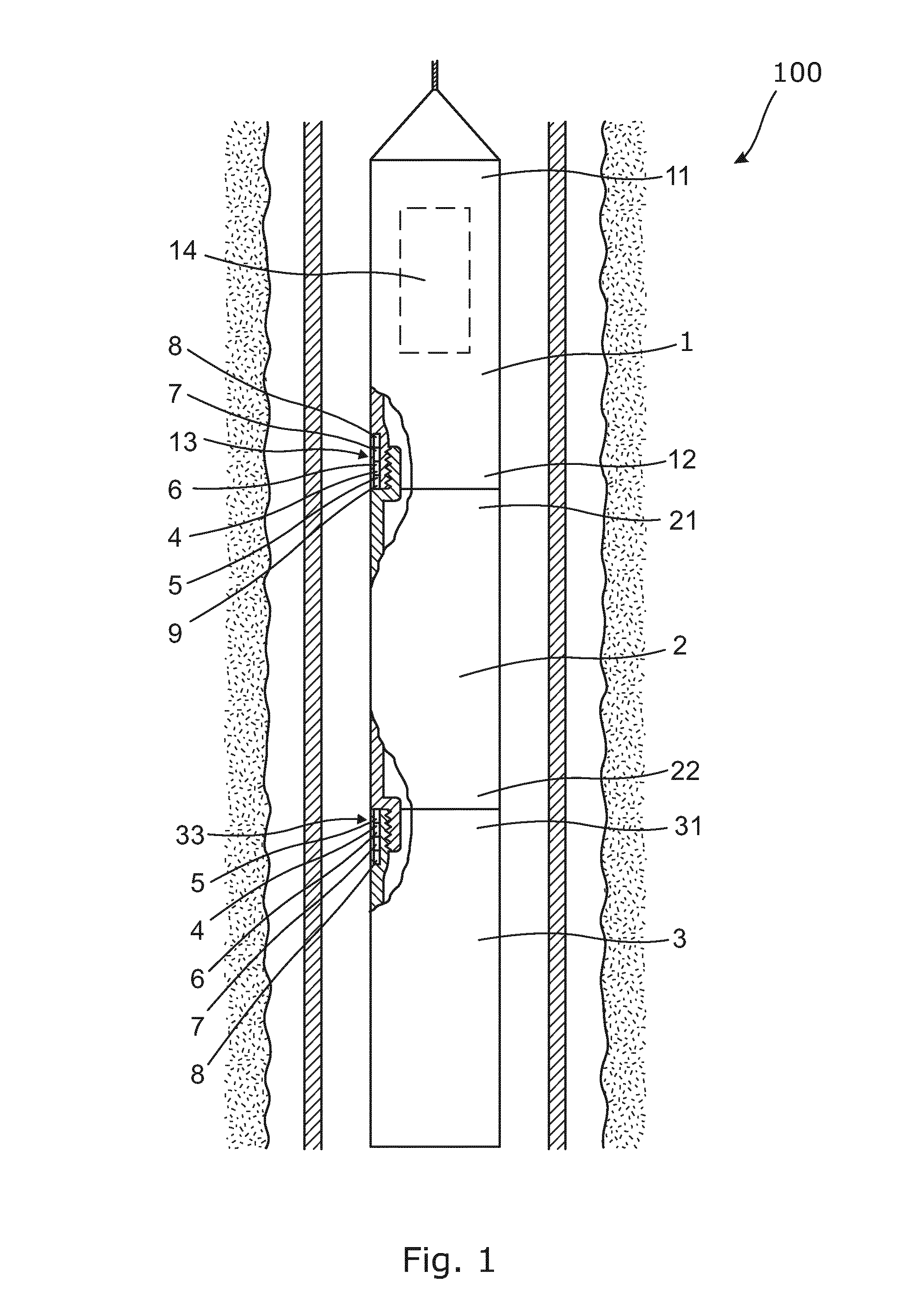
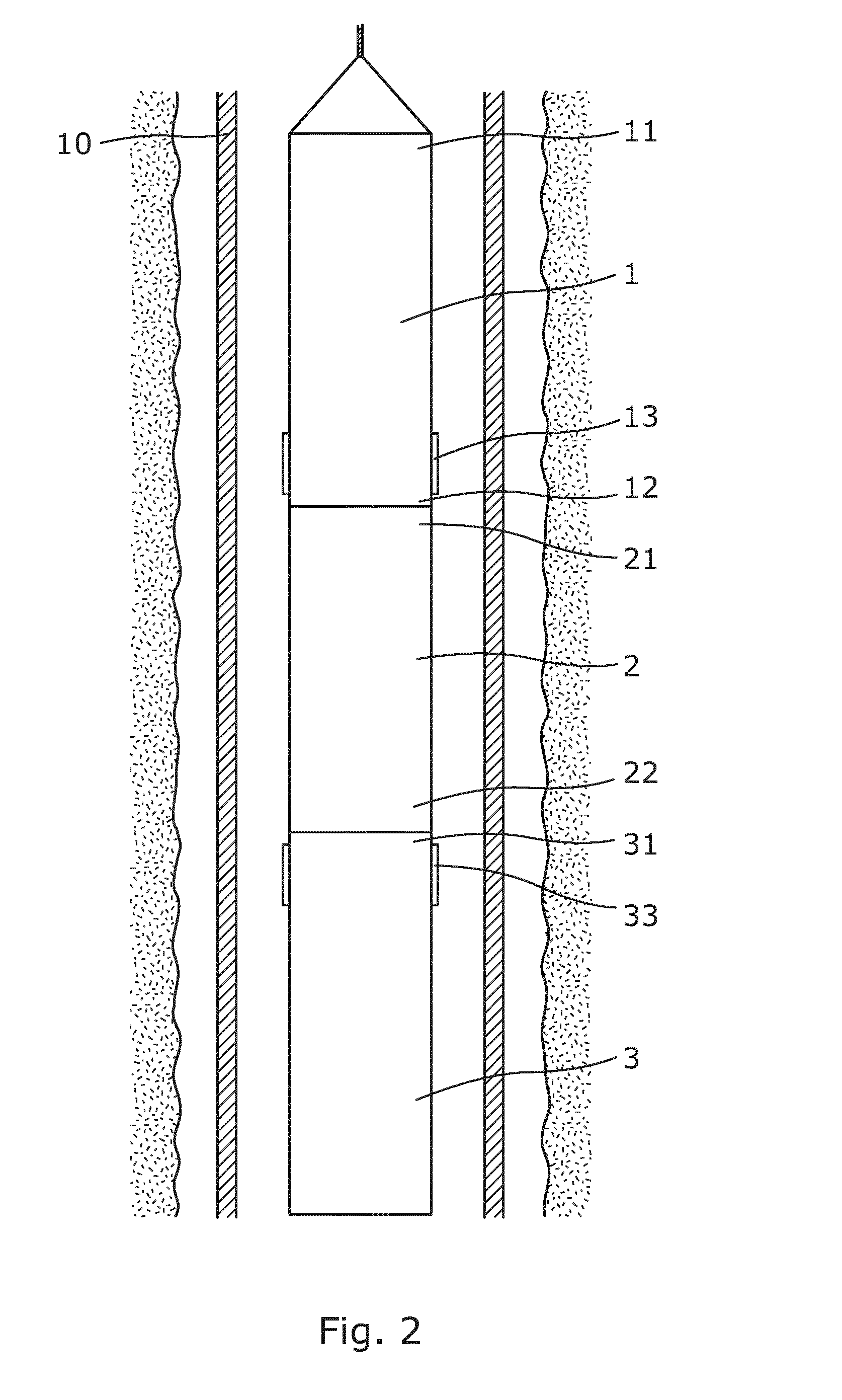
[0059]FIG. 1 shows a downhole tool system 1 comprising three tools; a first 1, a second 2 and a third 3 tool, arranged as a tool string. The first tool 1 is connected to a wireline at its first end 11 to power the tool string. In its second end 12, the first tool 1 is connected to a first end 21 of the second tool 2 by means of a threaded connection firmly connecting the first 1 and second 2 tools. In its second end 22, the second tool 2 is connected to a first end 31 of the third tool 3, also by means of a threaded connection.
[0060]Two operators may work together to perform a well operation in the sense that a tool of one operator is arranged between the tools of another operator. Thus, the first 1 and the third tool 3 come from a first operator and the second tool 2 comes from a second operator. Since the first 1 and third 3 tools are separated by the second tool 2, communication between the tools of the first operator cannot take place inside the tools in the conventional way since it is not possible to communicate through the second tool 2. This is due to the fact that the second operator uses a different communication system than the first operator and that it is not possible to pull wires through the intermediate tool without having to substantially reconstruct this tool.
[0061]Therefore, the first 1 and third 3 tools comprise communication devices 13, 33 in the form of acoustic devices. The acoustic device of the first tool 1 is arranged in a housing wall at the second end 12 of the first tool 1, abutting the first end 21 of the second tool 2, thereby being able to generate acoustic signals propagating axially along the housing 23 of the second tool 2. The acoustic device of the third tool 3 is arranged in a housing wall at the first end 31 of the third tool 3, abutting the second end 22 of the second tool 2, thereby also being able to generate acoustic signals propagating axially along the housing 23 of the second tool 2.
[0062]Each acoustic device comprises a transducer 5 facing the end of the housing 23 of the second tool 2. The transducers 5 may be magnetostrictive transducers transmitting acoustic signals in the form of longitudinal sonic waves along the housing 23 of the second tool 2.
[0063]In FIG. 2, the communication devices 13, 33 comprise antennas for sending and receiving radio waves having wavelengths of 1-2 cm. The antennas are arranged so that they project only partly from the outer faces of the first 1 and third 3 tools and extend parallel to the longitudinal extension of the tools. By having antennas transmitting signals with wavelengths of 1-2 cm, the radio waves propagate in the well fluid along the tool string without being substantially destroyed when hitting the wall of the tools 1, 2, 3 or the wall of the production casing 10.
[0064]The antennas are arranged in the housings of the first 1 and third 3 tools and are isolated from the other parts of the tools to improve the quality of the communication between the first 1 and third 3 tools.
[0065]The antennas may also be projecting parts of the tools and be projected as required and maintained inside the tools when the tool string is submerged into the casing 10.
[0066]FIG. 3 shows a communication device 13 of the first tool 1 (indicated by dotted lines) comprising an antenna 40 for communicating with another antenna 40 of the third tool 3 by sending and receiving radio waves. The antenna 40 of the second tool 3 has the same design as shown in FIG. 3. The antenna 40 comprises one or more ferrite rods 41. The antenna is a loop antenna wound around one or more ferrite rods, which increases the inductance without increasing the size of the antenna substantially. This is especially useful for downhole tools where the space is limited. The ferrite rods extend parallel to the tool axis 43 and have a distance to the centre of the tool. The rods are spaced apart along the circumference of the tool housing and are thus enclosed by the tool housing. In another embodiment, the antenna may be arranged in the tool housing. The ferrite rods are thus arranged in a circular loop connected with a processor 44. The processor 44, which is also referred to as a CPU, may use orthogonal frequency-division multiplexing (OFDM) modulation for transmitting encoding digital data on multiple carrier frequencies between the antennas.
[0067]As can be seen from FIG. 3, the antennas are arranged to face the third party tool 2.
[0068]The antenna comprises several rods, of which one half are used as antennas 41a and the other half are used as back-up antennas 41b. In the centre, an adaptive feedback sensor antenna is arranged.
[0069]By having rods, the antenna is able to send and receive at different frequencies—one frequency for each rod. The antennas transmit radio waves having a wavelength which is lower than 200 m, preferably lower than 1 m, more preferably lower than 10 cm, and even more preferably lower than 2.5 cm. Furthermore, the waves may be transmitted at a frequency of 520-1610 kHz.
[0070]Communication over 20 to 40 metres results in data rates between 150 kbps and 680 kbps using linear bandwidth of 1 MHz. If the third party tool being the second tool is smaller, resulting in communication over a shorter distance, the data rates are increased.
[0071]Thus, the antennas may be loop antennas, such as small loop antennas, loop stick antennas, or ferrite rod antennas. The antenna may be a multi-zone focussed antenna.
[0072]By fluid or well fluid is meant any kind of fluid that may be present in oil or gas wells downhole, such as natural gas, oil, oil mud, crude oil, water, etc. By gas is meant any kind of gas composition present in a well, completion, or open hole, and by oil is meant any kind of oil composition, such as crude oil, an oil-containing fluid, etc. Gas, oil, and water fluids may thus all comprise other elements or substances than gas, oil, and/or water, respectively.
[0073]By a casing is meant any kind of pipe, tubing, tubular, liner, string etc. used downhole in relation to oil or natural gas production.
[0074]In the event that the tools are not submergible all the way into the casing, a downhole tractor can be used to push the tools all the way into position in the well. A downhole tractor is any kind of driving tool capable of pushing or pulling tools in a well downhole, such as a Well Tractor®.
[0075]Although the invention has been described in the above in connection with preferred embodiments of the invention, it will be evident for a person skilled in the art that several modifications are conceivable without departing from the invention as defined by the following claims.

PUM

no PUM

Description & Claims & Application Information

We can also present the details of the Description, Claims and Application information to help users get a comprehensive understanding of the technical details of the patent, such as background art, summary of invention, brief description of drawings, description of embodiments, and other original content. On the other hand, users can also determine the specific scope of protection of the technology through the list of claims; as well as understand the changes in the life cycle of the technology with the presentation of the patent timeline. Login to view more.
Why Eureka
Try Eureka