Information display device and wireless remote controller

a technology of information display and wireless remote control, which is applied in the field of wearable information display, can solve the problems of affecting the operation of the device by the user, creating a bothersome feeling, and feeling as bothersome, and achieves the effect of weakening the intensity of light and reducing the degree of emphasis of images

Inactive Publication Date: 2013-10-10
NIKON CORP
View PDF8 Cites 157 Cited by
  • Summary
  • Abstract
  • Description
  • Claims
  • Application Information

AI Technical Summary

Benefits of technology

The invention allows for a display device to be constructed without interfering with the user's operation or causing discomfort. The wiring is connected from the display part to the accommodating part, which is on the side or rear of the head. The control part enhances the user's experience by reducing the intensity of light from the outside world that could interfere with the display.

Problems solved by technology

However, in cases where wiring is thus run directly from the control device 27 to the display part 25, this wiring cable 28 may interfere with the operation of the device by the user, and create a bothersome feeling.
However, under relatively safe use conditions such as indoor use, this switching inside the brain merely disturbs the feeling of immersion in the movie, and is therefore felt as bothersome.
In such cases, the eye that views the outside world may be strained, so that a difficult adjustment that relaxes the eye viewing the images becomes necessary, and the eyes of the user are fatigued.
However, since the controller 751 is ordinarily mounted on the belt or the like of the user or accommodated in a pocket or briefcase during use, there may be cases in which it is necessary to confirm the position of the controller 751 or receiving part 752 in order to send signal data from the remote controller 761, so that there is a problem in that the device is difficult to use.

Method used


Image

  • Information display device and wireless remote controller
  • Information display device and wireless remote controller
  • Information display device and wireless remote controller

Examples


Embodiment Construction

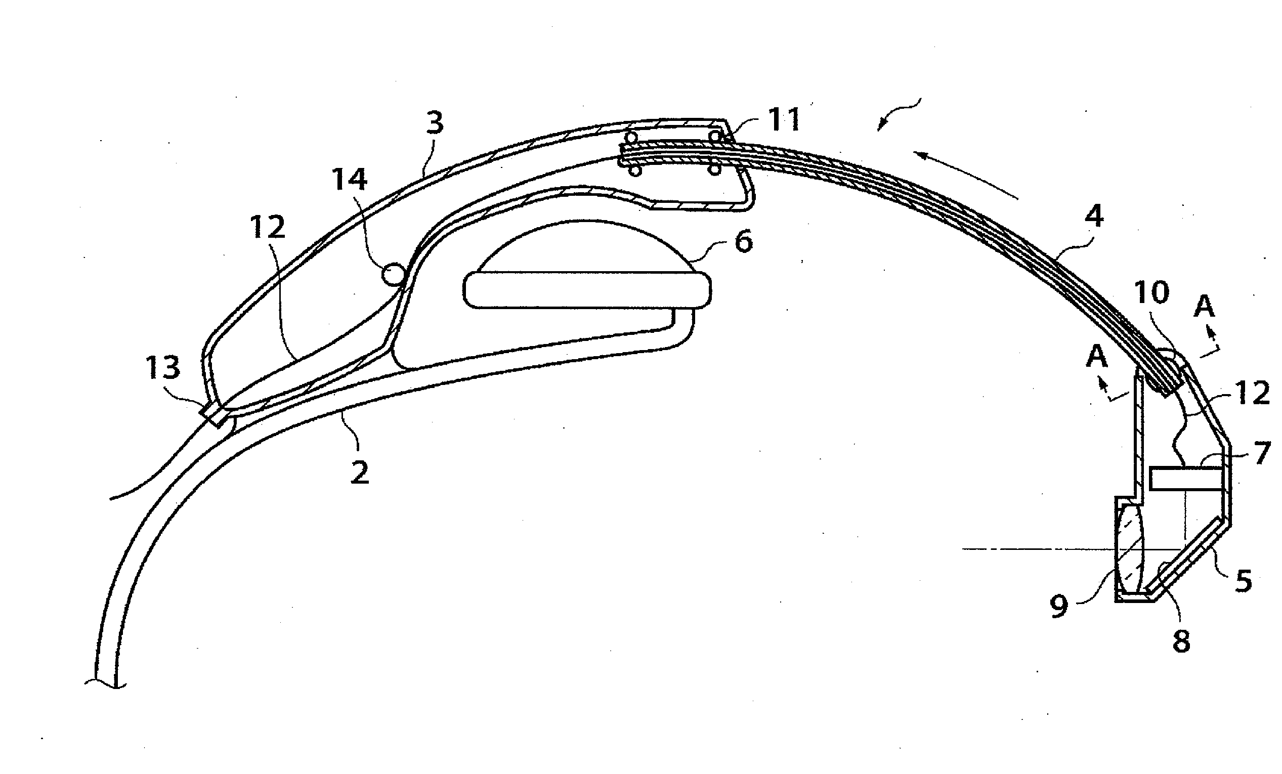
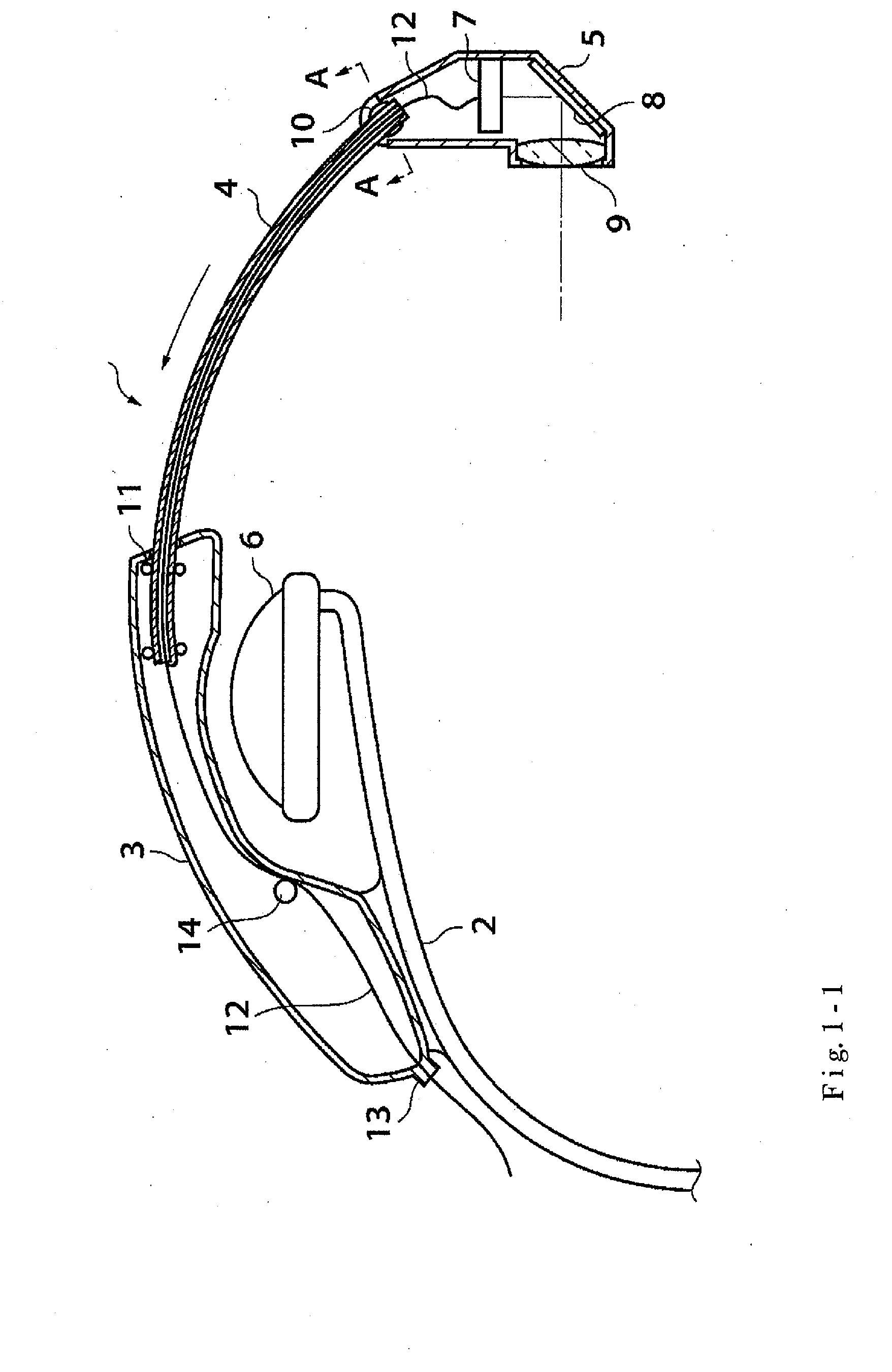
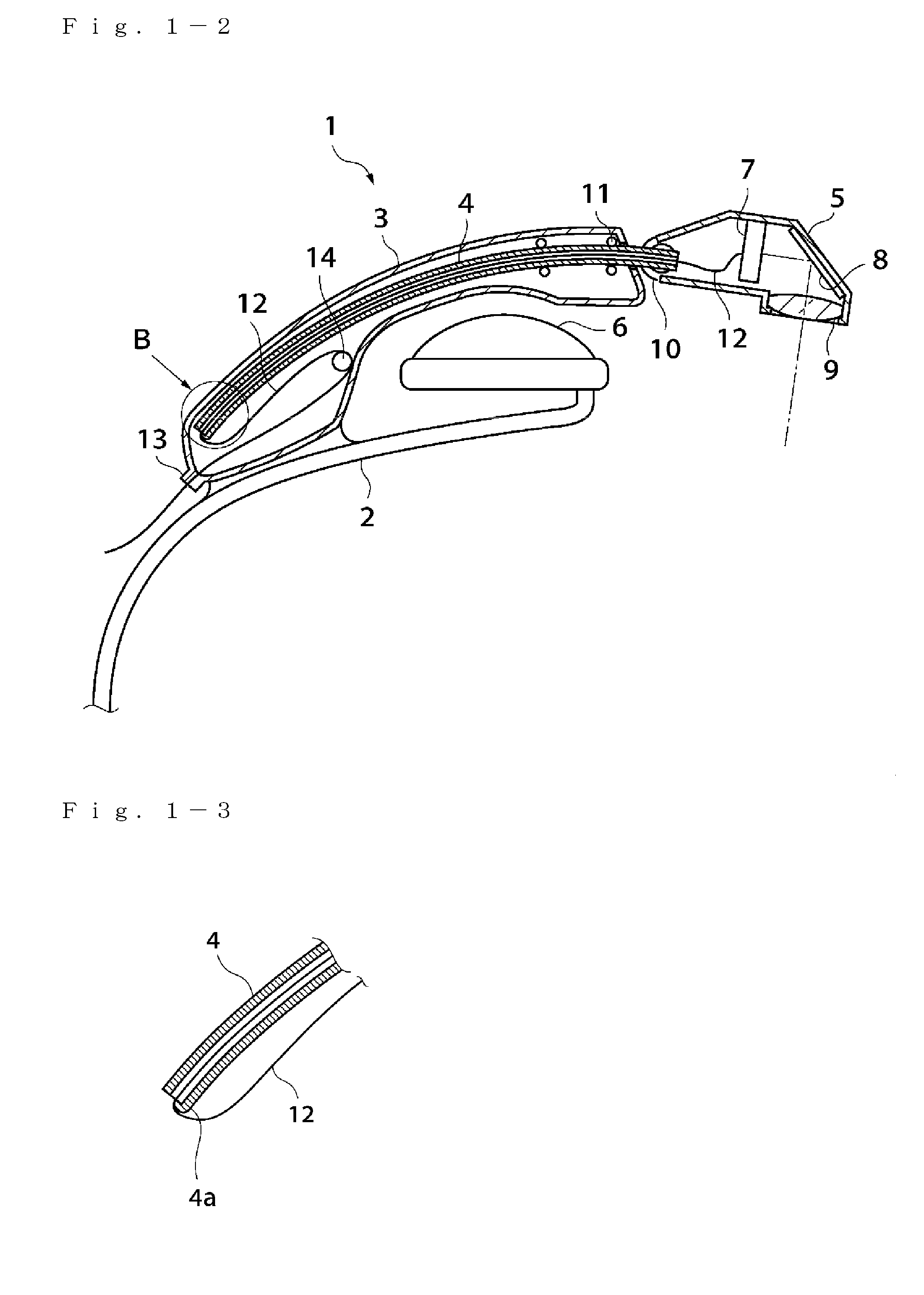
[0133]Working configurations of the present invention will be described below with reference to the figures. FIG. 1-1 is a diagram showing an outline of a head-mounted display constituting Working Configuration 1-1 of the present invention. This diagram is a sectional view which shows only the essential parts. Furthermore, this sectional view shows only the left half to which the display arm is attached.

[0134]The head-mounted display 1 comprises, as essential parts, a rear arm 2, an accommodating part 3 which is attached to the rear arm 2, a display arm 4 which is held so that this display arm can be accommodated in the accommodating part 3, a display part 5 which is attached to the tip end of the display arm 4 so that this display part 5 can pivot, and a headphones 6 which are disposed on both end parts of the rear arm 2. The rear arm 2 and one of the headphones 6 are also disposed on the right side.

[0135]An image display device 7 is disposed in the display part 5, and the system i...


PUM


Abstract

A head-mounted display has a rear arm, an accommodating part attached to the rear arm, a display arm that is held in the accommodating part, a display part which is pivotably attached to a tip end of the display arm, and headphones which are disposed on both end parts of the rear arm. A flat cable which supplies a power source and signals to the image display device is led into the accommodating part via a wiring attachment part, and is fastened to the accommodating part by the wiring attachment part. In the accommodating part, the intermediate part of the flat cable is fastened by a wiring retainer. The flat cable enters the display arm from the rear end part of the display arm, and is further conducted to the image display device inside the display part via a spherical-surface coupling.

Description

CROSS-REFERENCE TO RELATED APPLICATIONS[0001]This is a Divisional of U.S. application Ser. No. 12 / 556,506, filed Sep. 9, 2009, which is a Divisional of U.S. application Ser. No. 11 / 442,890, filed May 30, 2006, which is a continuation of PCT International Application No. PCT / JP2004 / 018440, filed Dec. 3, 2004, the entire contents of all of which are incorporated herein by reference.TECHNICAL FIELD[0002]The present invention relates to a wearable information display device such as a head-mounted display or near-eye display which is mounted on the head and used to observe video images, especially an information display device which shows both images and the outside world to the user, and a wireless remote controller that is used in such an information display device.BACKGROUND ART[0003]In recent years, various video image display devices of the eyeglass type have been proposed in which video images displayed on a display device such as a liquid crystal panel (LCD) are observed as enlarg...

Claims


Application Information

Patent Timeline
Patent Type & Authority Applications(United States)
IPC IPC(8): G02B27/01H04N5/74
CPCH04N5/7491G02B27/017G09G2360/144
Inventor KATO, SHIGERUMIYAKE, NOBUYUKIOOTSUKI, MASAKI
Owner NIKON CORP
Why Eureka
Try Eureka