
Metalized film capacitor and inverter smoothing capacitor for automobile

a technology of metal film capacitor and inverter, which is applied in the direction of fixed capacitor, fixed capacitor details, transportation and packaging, etc., can solve the problems of small non-uniformity in operation and apt heat generation of fuses, and achieve the improvement of fuses operation, widen the range of fuses width, and secure the effect of fuses

Active Publication Date: 2010-04-13
PANASONIC CORP
View PDF11 Cites 13 Cited by
  • Summary
  • Abstract
  • Description
  • Claims
  • Application Information

AI Technical Summary

Benefits of technology

The solution stabilizes fuse operability under high temperatures, increases withstand voltage, suppresses capacitance reduction, and allows for the use of thinner dielectric films, enhancing the capacitor's performance and suitability for high-temperature applications like vehicle inverter smoothing capacitors.

Problems solved by technology

Accordingly, since fuses do not overlap with each other, the fuses are apt to emit heat and their non-uniformity in operation is little.

Method used


Image

  • Metalized film capacitor and inverter smoothing capacitor for automobile
  • Metalized film capacitor and inverter smoothing capacitor for automobile
  • Metalized film capacitor and inverter smoothing capacitor for automobile

Examples


Embodiment Construction

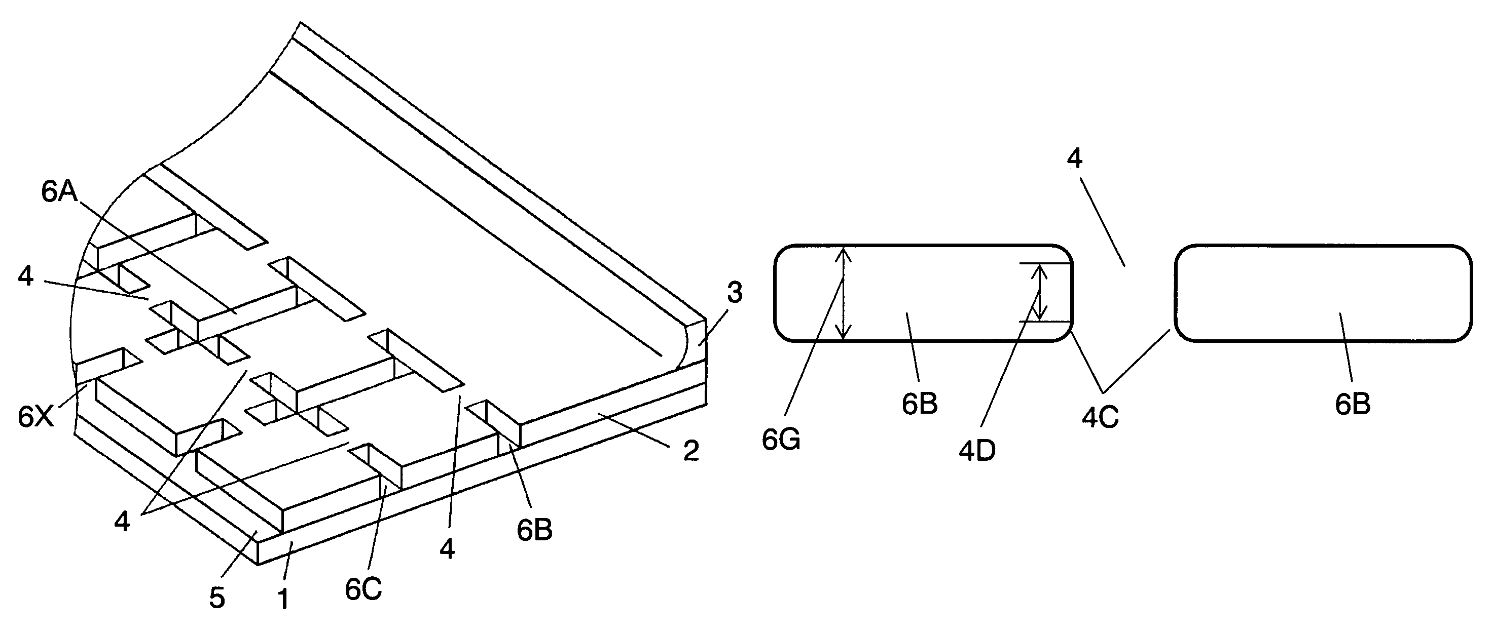
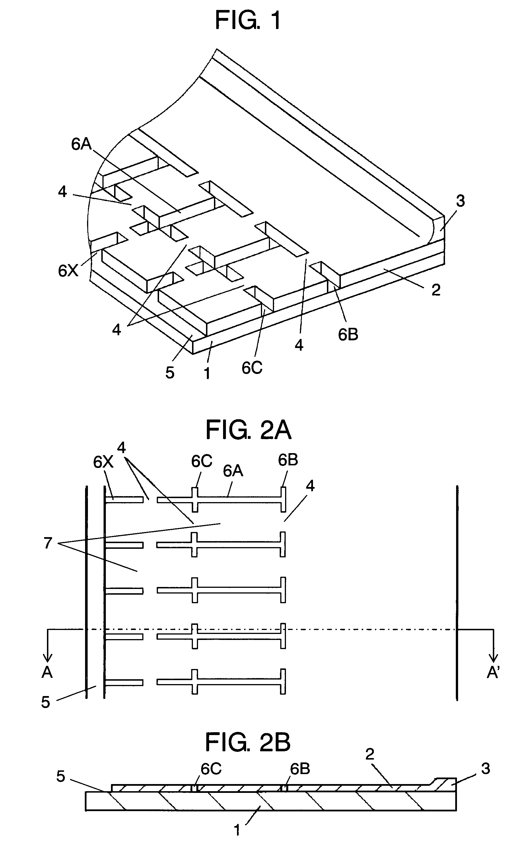
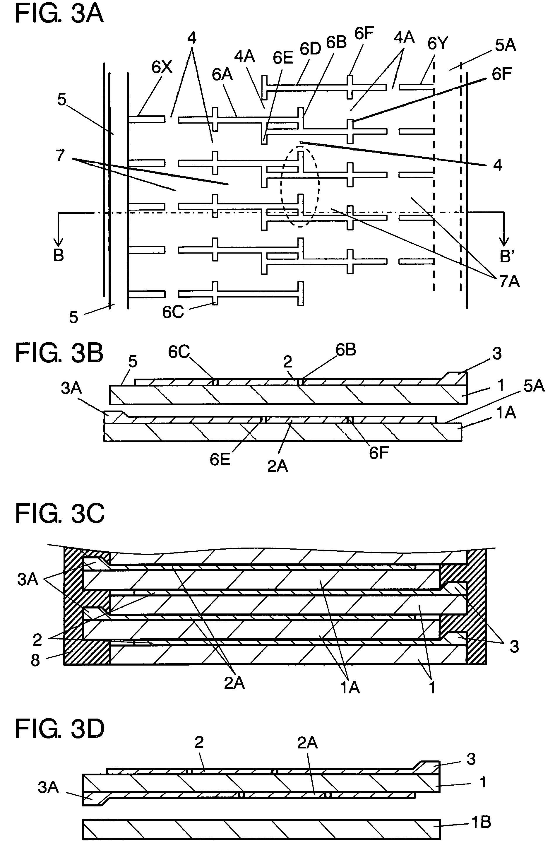
[0057]FIG. 1 is a perspective view of a metalized film according to an embodiment of the invention, FIG. 2A is a plan view of the metalized film shown in FIG. 1, and FIG. 2B is a sectional view taken along line A-A′ of FIG. 2A. FIG. 3A is a transparent plan view of a metalized film capacitor on which the metalized film shown in FIGS. 1 to 2B is laminated. FIG. 3B is a sectional view taken along line B-B′ of FIG. 3A. FIG. 3C is a sectional view of the film capacitor formed using the metalized film shown, in FIG. 1.

[0058]First metal deposition electrode including first high resistance portion (hereinafter abbreviated as high resistance portion) 2 and first low resistance portion (hereinafter abbreviated as low resistance portion) 3 are provided on a top surface as a first surface of first dielectric film (hereinafter abbreviated as film) 1 such as a polypropylene film. Low resistance portion 3 is formed along a first side in the longitudinal direction of film 1. First slits (hereinaft...


PUM


Abstract

A metalized film capacitor includes a metal deposition electrode on a dielectric film. The metal deposition electrode includes slits provided and divided only at a side opposite to low resistance portions connected to a metalized contact, and fuses provided between the slits. In a laminated metalized film, slits provided at a central portion in a width direction of the metalized deposition electrode and extending in the longitudinal direction of the dielectric film do not overlap with each other.

Description

TECHNICAL FIELD[0001]The present invention relates to a metalized film capacitor used in electric devices, various power supply circuits, communication devices, vehicles including electric automobiles, and so on.BACKGROUND ART[0002]Conventionally, an electrode of an electrode drawing portion in a wound plastic film capacitor having a self-security mechanism is formed to be thick. This increases strength of contact with a metalized contact which is an electrode introducing portion. Such a film capacitor is disclosed in Japanese Patent Unexamined Publication No. S62-183506.[0003]There has been known a self-security mechanism in which microscopic blocks are formed in a deposited electrode using slits in which metal is not deposited, and fuses provided between the slits are connected between the microscopic blocks, with divided electrodes interconnected in parallel. There has been also recently known a self-security mechanism that employs a divided electrode pattern having slits provide...

Claims


Application Information

Patent Timeline
Patent Type & Authority Patents(United States)
IPC IPC(8): H01G4/015H01G4/005
CPCH01G2/08H01G2/16H01G4/18H01G4/015Y02T10/7022Y02T10/70
Inventor OKUNO, SHIGEOSHIOTA, KOHEINAKATSUBO, KAZUHIRO
Owner PANASONIC CORP
Learn More