Detection device and gesture input device

a detection device and gesture technology, applied in the direction of dashboard fitting arrangements, instruments, transportation and packaging, etc., can solve the problems of erroneous recognition, high operation burden, and ambiguous input condition when the user returns the palm, so as to reduce the risk of accidents, and reduce the effect of operation burden

Inactive Publication Date: 2016-12-01
DENSO CORP
View PDF3 Cites 15 Cited by
  • Summary
  • Abstract
  • Description
  • Claims
  • Application Information

AI Technical Summary

Benefits of technology

[0026]When the angular velocity obtained from the steering angle sensor is as high as or higher than the threshold, it means that the operator is making a considerably large rotational operation on the steering wheel. The control portion therefore disables an input of a gesture. Hence, because the operator is able to concentrate on the driving of the vehicle, a contribution to safety of driving can be made.
[0027]On the other hand, when the angular velocity obtained from the steering angle sensor is lower than the threshold, a rotational operation on the steering wheel by the operator is small and a sufficient time is left for the operator to make a gesture. By enabling an input of a gesture as originally designed in such a case, an input by a gesture of the operator can be more convenient.

Problems solved by technology

According to Patent Literature 1, however, an operation burden is high because when the operator makes an input operation while driving, the operator has to move the hand off the steering wheel to place the hand to the predetermined operation region.
Conversely, it is not preferable to enable an input by a gesture when a rotational operation on the steering wheel is tough for reason of safety of driving.
Such a technical idea, however, indicates that an input condition when the user returns the palm is quite ambiguous.
For example, when the user returns the palm swiftly after the user sweeps the palm to the right (or to the left), it may be erroneously recognized that the user made an input in an opposite direction.
That is to say, when the user wishes to scroll the objects in succession in one direction, the objects may be scrolled back and forth repetitively due to erroneous recognition.
The user thus becomes unable to make input operations of a same content in series.

Method used


Image

  • Detection device and gesture input device
  • Detection device and gesture input device
  • Detection device and gesture input device

Examples


first embodiment

Modifications of First Embodiment

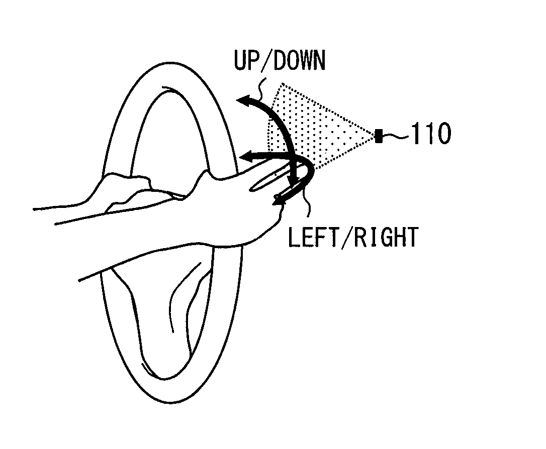
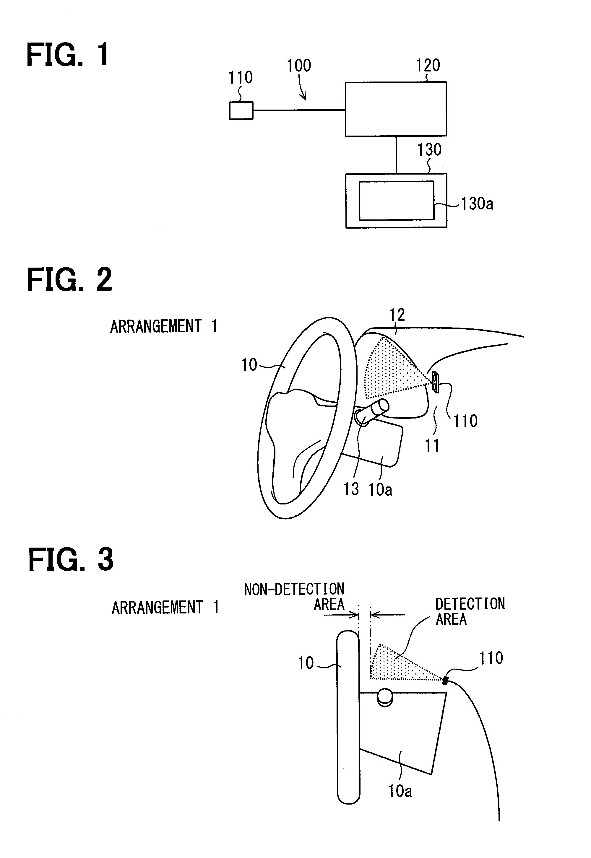
[0069]In the first embodiment above, the sensor 110 is disposed to the instrument panel 11 in close proximity to the steering column 10a and located so as to oppose the right hand of the driver who is holding the steering wheel 10 with the right and left hands placed at 2 o'clock and 10 o'clock positions respectively when viewed in the vehicle travel direction from the driver's seat. Hence, the optical axis of the sensor 110 extends substantially in a horizontal direction from the instrument panel 11 to in front of (back surface of) the steering wheel 10 (first location of FIG. 2 and FIG. 3).

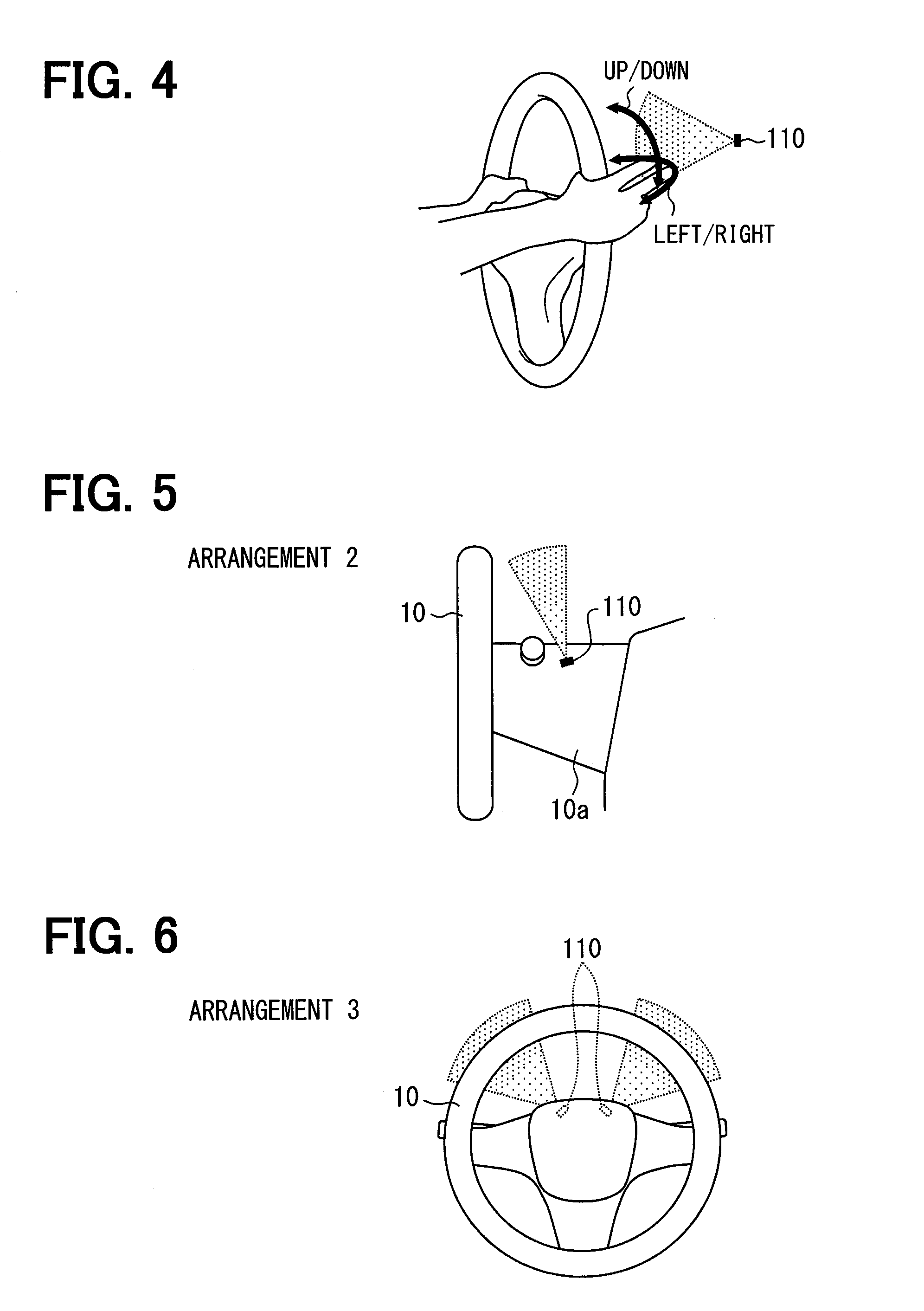
[0070]However, the location of the sensor 110 is not limited to the first location specified above, and the sensor 110 may be located at, for example, a second location through a sixth location as are shown in FIG. 5 through FIG. 9, respectively.

[0071]In the case of the second location as shown in FIG. 5, in contrast to the first location, the sensor 110 is provi...

second embodiment

[0077]FIG. 11 and FIG. 12 show a detection device 110 and an operation input device 100A of a second embodiment. In contrast to the first embodiment above, the second embodiment is configured to prevent an erroneous input of a gesture when a turn-signal lever 13 is operated.

[0078]When the turn-signal lever 13 is operated (an input is made), an operation signal (input signal) is inputted into a sensor 110. The turn-signal lever 13 corresponds to a switch portion of the present disclosure. Because the turn-signal lever 13 is provided to a steering column 10a, when a driver operates the turn-signal lever 13, a finger enters a detection area of the sensor 110. When a motion of a finger during an operation on the turn-signal lever 13 is detected as a gesture in a top-bottom direction, a display content of a display portion 130a may possibly be changed against an intention of the driver.

[0079]The present embodiment prevents such an erroneous input by performing an erroneous input preventi...

third embodiment

[0085]A gesture input device 100 of a third embodiment will be described using FIG. 14 through FIG. 16. The gesture input device 100 of the present embodiment operates a vehicle device 130 according to a motion of a particular part of a body of a driver (operator).

[0086]A vehicle is provided with a steering wheel 10 used to steer the vehicle, an instrument panel 11 located behind the steering wheel 10 (front side of the vehicle), a combination meter 12 collectively displaying various types of vehicle information and located in the instrument panel 11 so as to oppose an upper half of the steering wheel 10, and so on.

[0087]The gesture input device 100 includes an action detection portion 110 and a control portion 120. In the gesture input device 100, the control portion 120 switches a display image on a display portion 130a of the vehicle device 130 and makes an operation input to the the vehicle device 130 according to a motion of the body of the driver detected by the action detecti...


PUM


Abstract

A detection device installed to a vehicle to detect a gesture of a finger of an operator includes: a detection portion disposed to a steering column of the vehicle or in close proximity to the steering column to detect a space within a predetermined range toward a steering wheel; and a switch portion arranged behind the steering wheel and operated by the operator. The detection portion determines whether the input signal is inputted from the switch portion within a fixed time period after the detection portion detects the gesture of the finger of the operator. The gesture is made valid when the input signal fails to be inputted into the detection portion. The gesture is made invalid when the input signal is inputted into the detection portion.

Description

CROSS REFERENCE TO RELATED APPLICATION[0001]This application is based on Japanese Patent Application No. 2014-43142 filed on Mar. 5, 2014, Japanese Patent Application No. 2014-59332 filed on Mar. 21, 2014, and Japanese Patent Application No. 2014-77882 filed on Apr. 4, 2014, the disclosures of which are incorporated herein by reference.TECHNICAL FIELD[0002]The present disclosure relates to a detection device detecting a gesture operation of an operator and a gesture input device enabling an input by gesture of an operator.BACKGROUND ART[0003]An operation input device described in Patent Literature 1 includes a camera that captures an image around a driver's seat. A gesture of a hand of an operator is detected from an image captured by the camera. An operation intended by the operator is determined from the detected gesture. Also, a device installed to a vehicle is operated according to the determined operation.[0004]More specifically, a first operation region corresponding to an upp...

Claims


Application Information

Patent Timeline
Patent Type & Authority Applications(United States)
IPC IPC(8): G06F3/01B60K37/06
CPCG06F3/017B60K37/06B60K2350/901B60K2350/928B60K2350/1052B60K2370/1464B60K2370/48B60K2370/146B60K2370/736B60K2370/782
Inventor TSUDA, YOSHIYUKI
Owner DENSO CORP
Why Eureka
Try Eureka