Roller crusher having at least one roller comprising a flange

a technology of roller crusher and flange, which is applied in the field of roller crusher, can solve the problems of inability to vary the roller parameters to the desired extent, and reduce the crushing result at the edges of the roller, and achieve the effect of reducing the crushing resul

Active Publication Date: 2013-10-24
METSO SWEDEN AB
View PDF4 Cites 6 Cited by
  • Summary
  • Abstract
  • Description
  • Claims
  • Application Information

AI Technical Summary

Benefits of technology

[0005]It is an object of the present invention to provide an improvement of the prior art. More particularly, it is an object of the present invention to provide a roller crusher for which the roller diameter and the roller width can be varied more freely without a reduced crushing result.
[0007]A roller crusher having two generally parallel rollers arranged to rotate in opposite directions, towards each other, and separated by a gap is provided. Each roller has a first end and a second end. The roller crusher comprises a flange attached to at least one of the ends of one of the rollers. The flange extends in a radial direction of the roller, and has a height above an outer surface of the roller which is sufficient to extend across the gap substantially along a nip angle of the roller crusher. This is advantageous in that the flange eliminates the weakness spot at the edge of the rollers. The flange will help maintaining the material on the outer roller surface. That is to say, due to the flange, the material is prevented from falling over the edge of the roller. This will in turn help increasing the pressure on the material towards the gap between the rollers at the edge of the rollers. By eliminating the weakness spot at the edge of the rollers, the roller diameter and the roller width can be varied more freely without a reduced crushing result. Additionally, the flanges will facilitate the providing of an autogenous protection layer on the rollers, consisting of the material to be crushed.
[0009]The flange may comprise a feeding structure on the inside of the flange, said structure extending from the inside of the flange towards the other end of the roller. This is advantageous in that the structure will help increasing the pressure on the material towards the gap between the rollers at the edge of the roller even further. The structure will engage with the material which will be moved inside the crushing area and the pressure will be optimized.
[0011]The flange may be made of a first material and the structure of a second material, said second material being harder than said first material. This way, the structure will act as a wear-resistant element and protect the flange from wear. The structure will also help creating and holding an autogenous protection layer on the flange.
[0012]The flange may be divided into a plurality of segments, which is advantageous in that both the manufacturing and mounting of the flange will be facilitated. The flange may be attached to the roller by means of adhesive, bolting, screwing, welding, brazing or any other suitable fastening technique.

Problems solved by technology

A general problem associated with existing high pressure grinding rollers is that the ratio between the roller diameter and the roller width is very important due to a significant edge effect, i.e. the crushing result is reduced at the edges of the rollers.
Thus, these roller parameters cannot be varied to the desired extent.

Method used


Image

  • Roller crusher having at least one roller comprising a flange
  • Roller crusher having at least one roller comprising a flange
  • Roller crusher having at least one roller comprising a flange

Examples


second embodiment

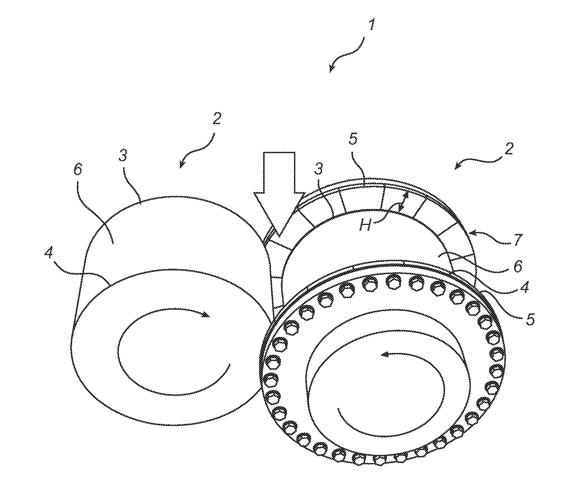
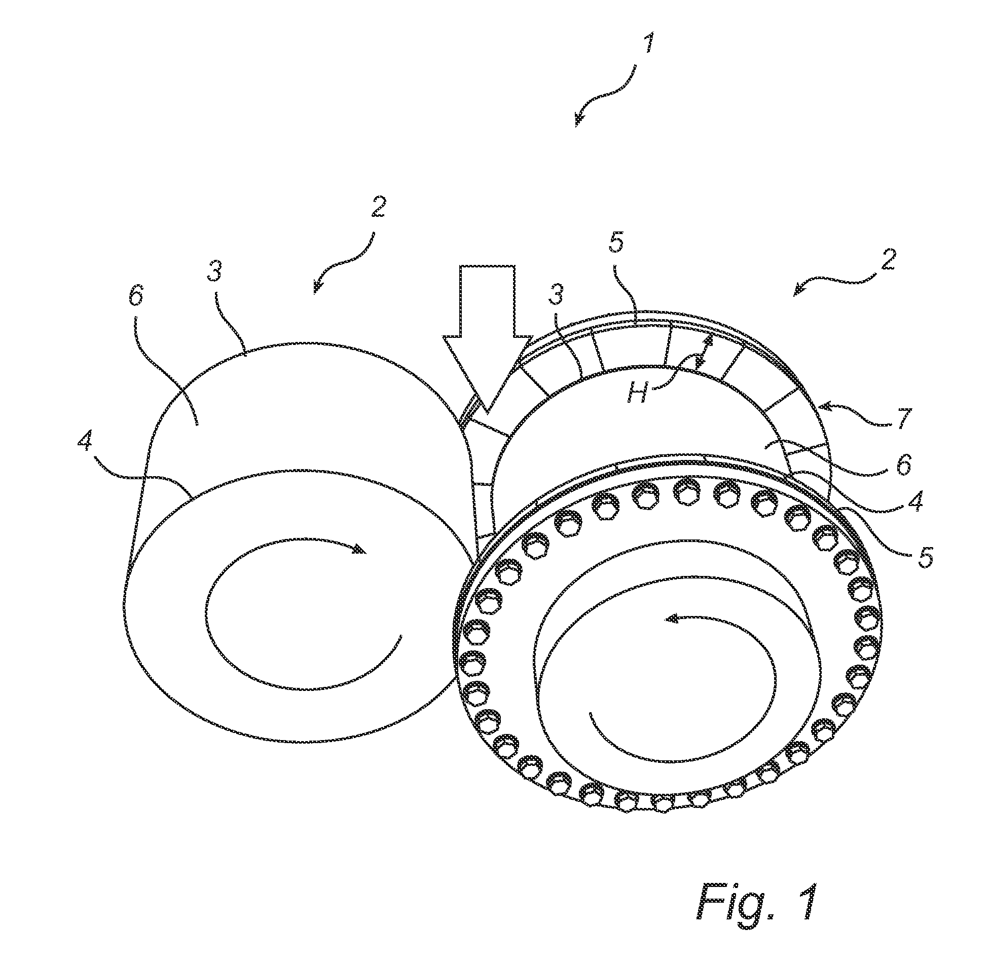
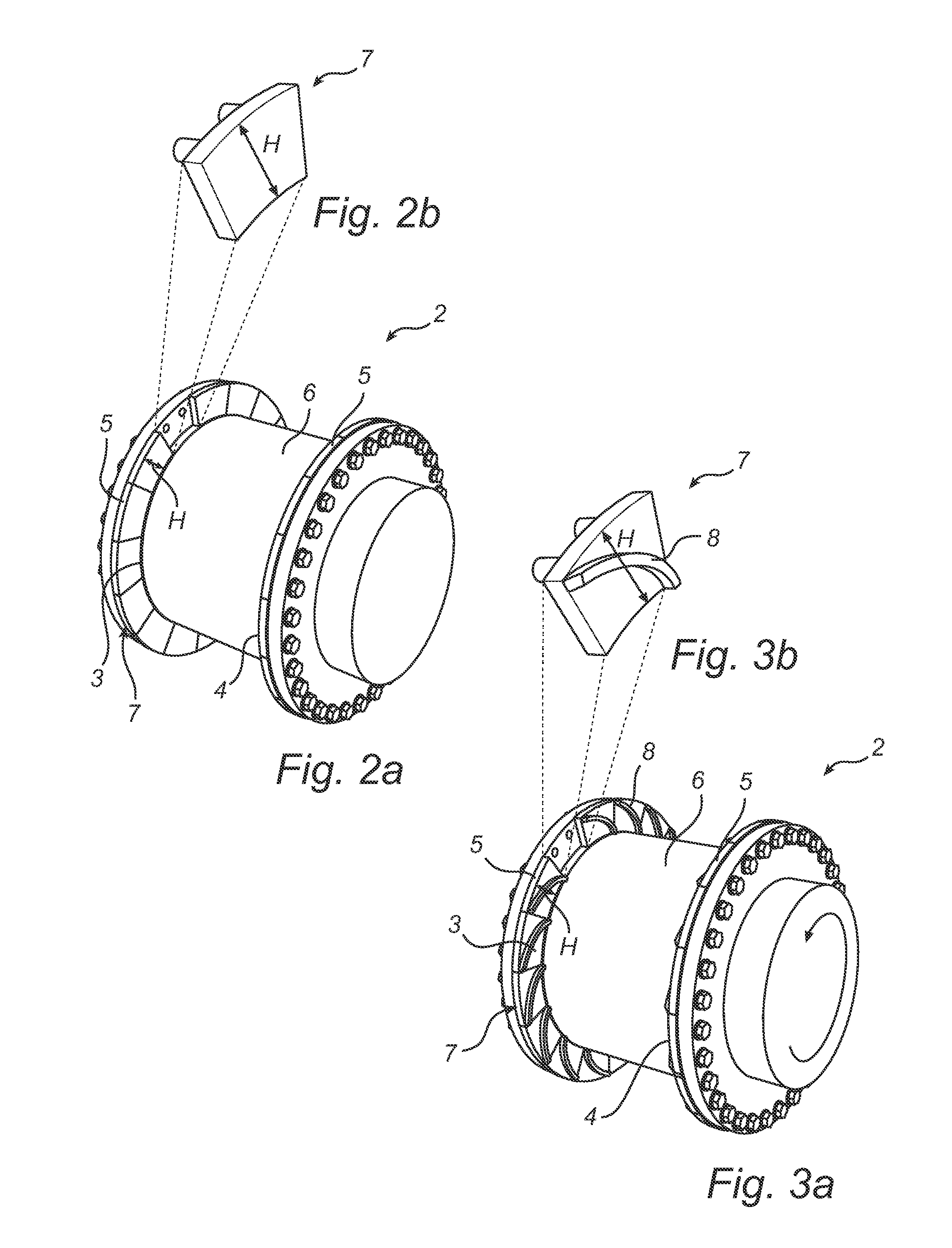
[0027]In FIG. 3a, the roller 2 of the roller crusher 1 is illustrated. Here, the flanges 5 comprise a feeding structure 8 on the inside of the flanges 5. The structure 8 extends from the inside of the flange 5 towards the other end 3, 4 of the roller 2. The structure 8 is continuous and arcuate.

[0028]The structure 8 will increase the pressure on the material towards the gap between the rollers 2 at the edge of the roller 2. The material will engage with the structure 8 and be pressured towards and through the gap, i.e. the material will be choke-fed into the gap.

[0029]FIG. 3b illustrates a segment 7 of the flange 5 in FIG. 3a. Naturally, also the flanges 5 according to this second embodiment can be designed as one single unit.

third embodiment

[0030]In FIG. 4a, the roller 2 of the roller crusher 1 is illustrated. Here, the flanges 5 also comprise a feeding structure 8 on the inside. However, the structure 8 according to this embodiment is intermittent.

[0031]FIG. 4b illustrates a segment 7 of the flange 5 in FIG. 4a. Naturally, also the flanges 5 according to this third embodiment can be designed as one single unit.

[0032]In FIG. 5, a side view of the roller crusher 1 is illustrated in order to facilitate the understanding of the nip angle α. A first straight line has been drawn from the centre of the right roller 2 to and through a point on the left roller 2, at which point an active engagement between the left roller 2 and the material to be crushed is started. The nip angle α is measured between the horizontal plane extending through the centre of the left and right roller, and said first straight line. It is the smaller of the two possible angles which can be obtained in accordance with the definition presented above. I...


PUM


Abstract

The invention relates to a roller crusher having two generally parallel rollers arranged to rotate in opposite directions, towards each other, and separated by a gap, each roller having a first end and a second end. The roller crusher comprises a flange attached to at least one of said ends of one of said rollers. The flange extending in a radial direction of said roller, and has a height above an outer surface of said roller which is sufficient to extend across said gap substantially along a nip angle of said roller crusher.

Description

TECHNICAL FIELD[0001]The invention relates to a roller crusher having two generally parallel rollers arranged to rotate in opposite directions, towards each other, and separated by a gap, each roller having a first end and a second end.BACKGROUND ART[0002]When crushing or grinding rock, ore, cement clinker and other hard materials roller crushers may be used having two generally parallel rolls which rotate in opposite directions, towards each other, and which are separated by a gap. The material to be crushed is fed by gravity or choke-fed into the gap. One type of roller crusher is called high pressure grinding rollers or high pressure roller crushers. This type of roller crusher uses a crushing technique called interparticle crushing. Here, the material to be crushed or pulverised is crushed not only by the crushing surface of the rolls, but also by particles in the material to be crushed, hence the name interparticle crushing.[0003]One example of a high pressure grinding roller i...

Claims


Application Information

Patent Timeline
Patent Type & Authority Applications(United States)
IPC IPC(8): B02C4/30
CPCB02C4/30B02C4/305B02C4/283
Inventor GRONVALL, LARS
Owner METSO SWEDEN AB
Why Eureka
Try Eureka