Image forming apparatus capable of correcting relative position between laser beams

a technology of relative position and laser beam, which is applied in the direction of electrographic process apparatus, instruments, printing, etc., can solve the problems of limiting the adjustment of the focus position by the f- lens, the adjustment of the entire scanning length and the adjustment of the writing start position alone, and the damage of the image caused by moisture and like effects

Active Publication Date: 2013-10-31
CANON KK
View PDF8 Cites 13 Cited by
  • Summary
  • Abstract
  • Description
  • Claims
  • Application Information

AI Technical Summary

Benefits of technology

[0016]According to the present invention, when an image is formed by a plurality of laser beams, it is possible to properly correct exposure position shifts in the scanning direction between the laser beams.

Problems solved by technology

On the other hand, in the image forming apparatus that forms an electrostatic latent image on the photosensitive drum using a plurality of laser beams, deviation of the relative positional relationship between dots (pixels) formed by respective laser beams from a desired positional relationship produces a periodical image shift, which causes moiré and like harmful effects on an image.
In such a case, the adjustment of the entire scanning length and the adjustment of the writing start position alone are not enough for the adjustment of the dot position shift.
However, there is a limit to adjustment of the focus position by the f-θ lens, and hence the above-mentioned field curvature occurs, i.e. the focus position varies with each position on the scanning surface.

Method used


Image

  • Image forming apparatus capable of correcting relative position between laser beams
  • Image forming apparatus capable of correcting relative position between laser beams
  • Image forming apparatus capable of correcting relative position between laser beams

Examples


first embodiment

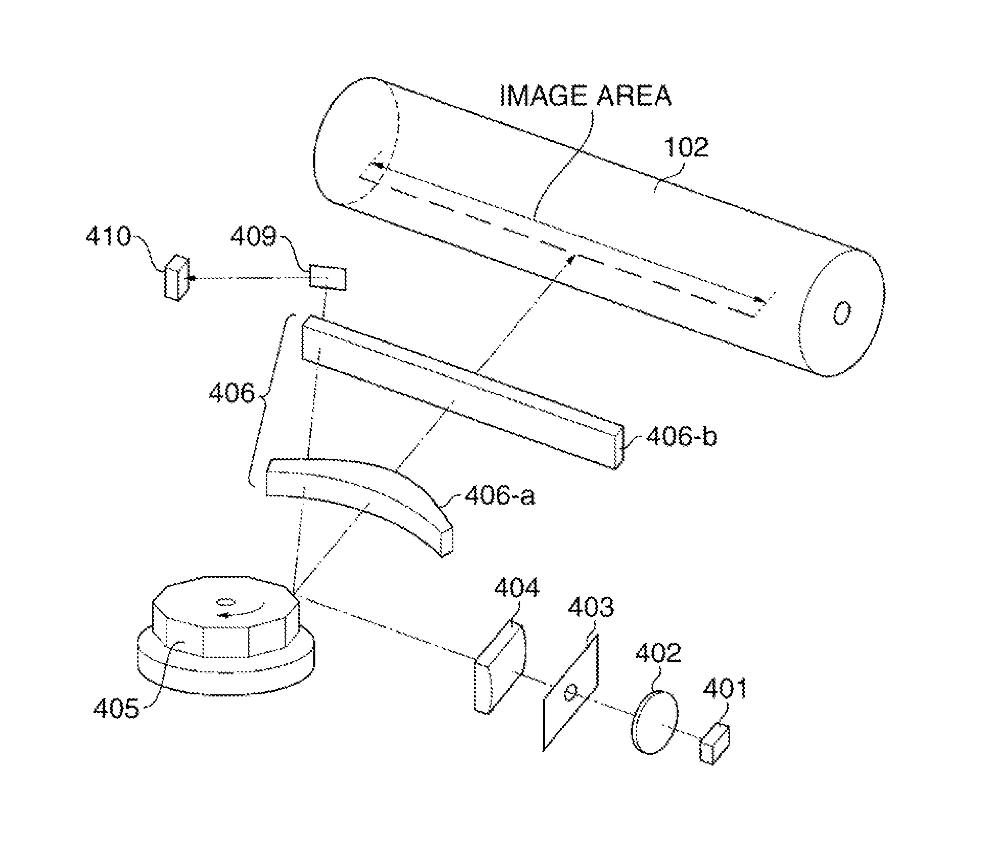
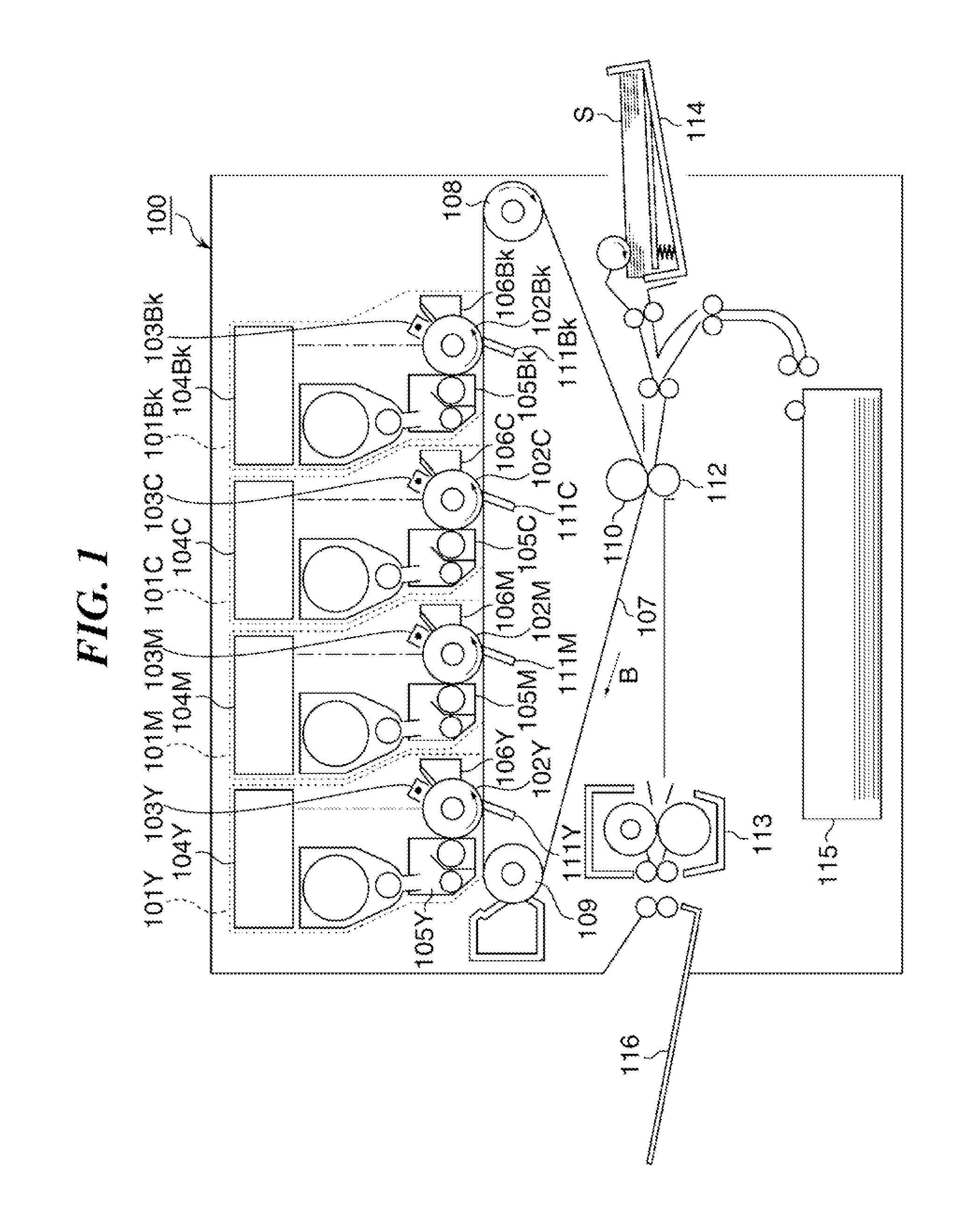
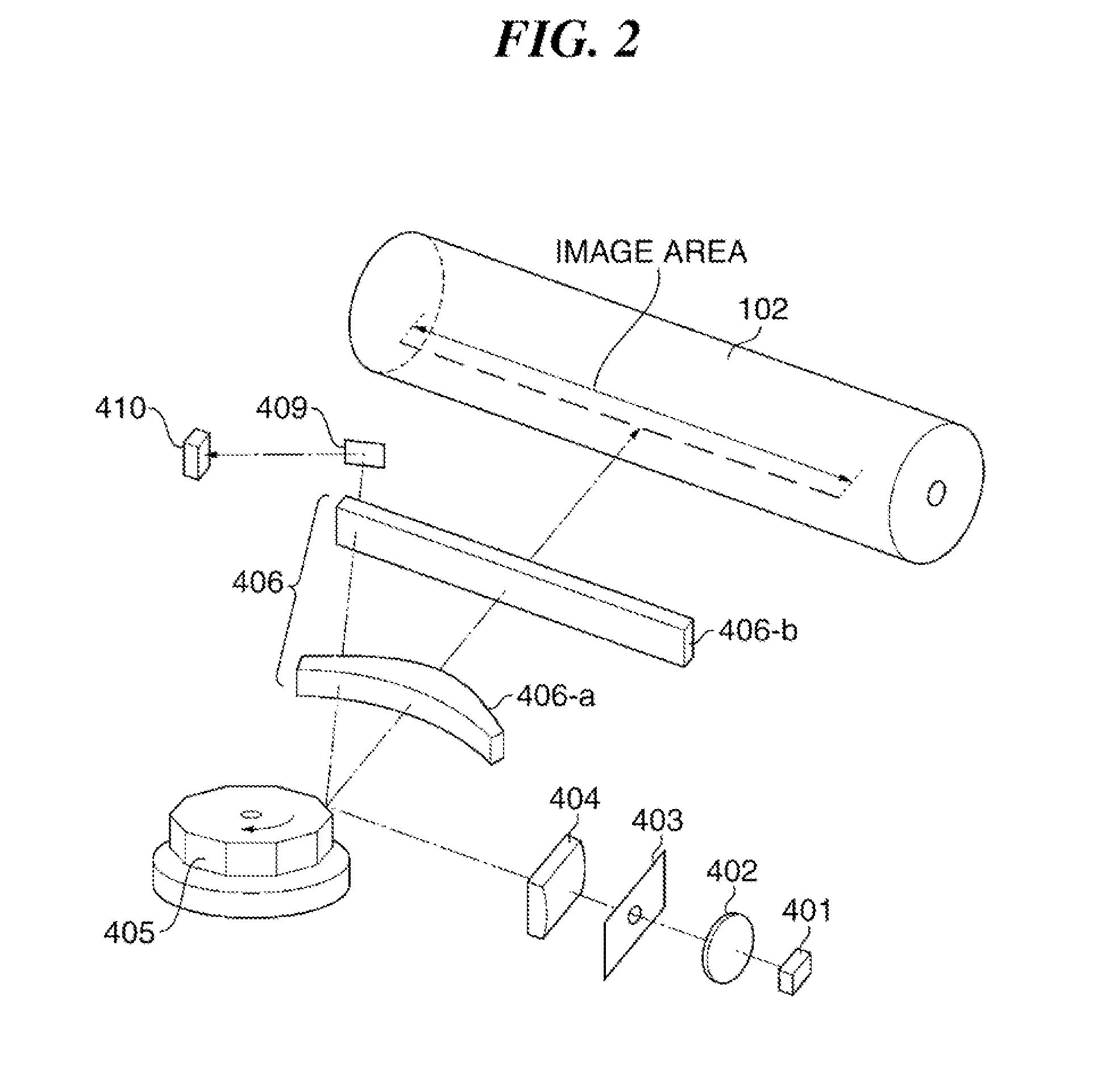
[0034]FIG. 1 is a schematic cross-sectional view of an image forming apparatus according to the present invention.

[0035]First, an outline will be given of control performed by the image forming apparatus 100. The image forming apparatus 100 adjusts dot positions in the main scanning direction between laser beams (light beams) according to a scanning position in the main scanning direction which is a direction in which the laser beams scan. The dot positions are adjusted by adjusting a writing start position on a beam-by-beam basis and performing magnification adjustment in each of a plurality of areas separated in the main scanning direction (hereinafter referred to as partial magnification adjustment). A detailed description of the control will be given hereafter.

[0036]The image forming apparatus 100 is constructed as a digital full color printer (color image forming apparatus) that forms an image using a plurality of color toners. In the present embodiment, although the color imag...

second embodiment

[0123]FIG. 8A is a flowchart of the print job execution process executed in the

[0124]FIG. 8B is a flowchart of an image forming process executed in a step S207 of FIG. 8A.

[0125]In steps S201 to S206, the CPU 501 executes the same processing as in the steps S101 to S106 of FIG. 6. Particularly in the step S206, the writing start position adjustment values and the partial magnification adjustment values are calculated in association with the respective mirror surfaces of the polygon mirror 405.

[0126]In the step S207, the CPU 501 executes the image forming process in FIG. 8B to thereby form a one-page image while setting adjustment values according to each mirror surface of the polygon mirror 405. In steps S208 and S209, the CPU 501 executes the same processing as in the steps S109 and S110 of FIG. 6.

[0127]In a step S301 in FIG. 8B, the CPU 501 issues an instruction for starting to rotate the polygon mirror 405. In a step S302, the CPU 501 determines whether or not the rotational speed...


PUM


Abstract

An image forming apparatus capable of correcting relative position in exposure position between laser beams that scan a photosensitive drum in a scanning direction of the laser beams. A semiconductor laser includes first and second light emitting elements for emitting first and second laser beams. These elements are arranged such that the laser beams expose positions on the photosensitive drum different in the sub scanning direction. A polygon mirror deflects the laser beams to scan the photosensitive drum. Relative position in the scanning direction between images to be formed on the photosensitive drum by exposure by the first and second laser beams is corrected based on correction data. An image data generation section generates drive signals associated with the respective light emitting elements. A semiconductor laser drive circuit causes the semiconductor laser to emit the first and second laser beams, based on the drive signals.

Description

BACKGROUND OF THE INVENTION[0001]1. Field of the Invention[0002]The present invention relates to an image forming apparatus based on an electrophotographic method, which exposes a photosensitive member to a plurality of laser beams.[0003]2. Description of the Related Art[0004]It is conventionally known that in an image forming apparatus based on an electrophotographic method, such as a laser printer or a copying machine, a light beam scanning device that emits laser beams is generally used to form an electrostatic latent image on a photosensitive drum (photosensitive member).[0005]The image forming apparatus based on the electrophotographic method uses a light beam scanning device. The light beam scanning device deflects a laser beam converted to a collimated laser beam by a collimator lens, using a polygon mirror, and the deflected laser beam is passed through an elongated f-θ lens to form an image on the photosensitive drum. The light beam scanning device of this type employs a me...

Claims


Application Information

Patent Timeline
Patent Type & Authority Applications(United States)
IPC IPC(8): B41J2/385
CPCG03G15/0435G03G15/043G02B26/12G03G15/04
Inventor FURUTA, YASUTOMOKONDO, SHUNSAKU
Owner CANON KK
Why Eureka
Try Eureka