
Display device

a display device and display screen technology, applied in the field of display devices, can solve the problems of inability to adjust the coordinate range of the touch panel, the difference between the input target location and the input location on the touch panel, and the inability to correct the input location to the location

Inactive Publication Date: 2016-07-07
SHARP KK
View PDF5 Cites 8 Cited by
  • Summary
  • Abstract
  • Description
  • Claims
  • Application Information

AI Technical Summary

Benefits of technology

The present invention allows for correcting shifts in touch location caused by the user's hand holding the touch pen. This technology can adjust the coordinate range on the touch panel and accurately locate the input location.

Problems solved by technology

In such a case, it is not possible to appropriately adjust the coordinate range on the touch panel.
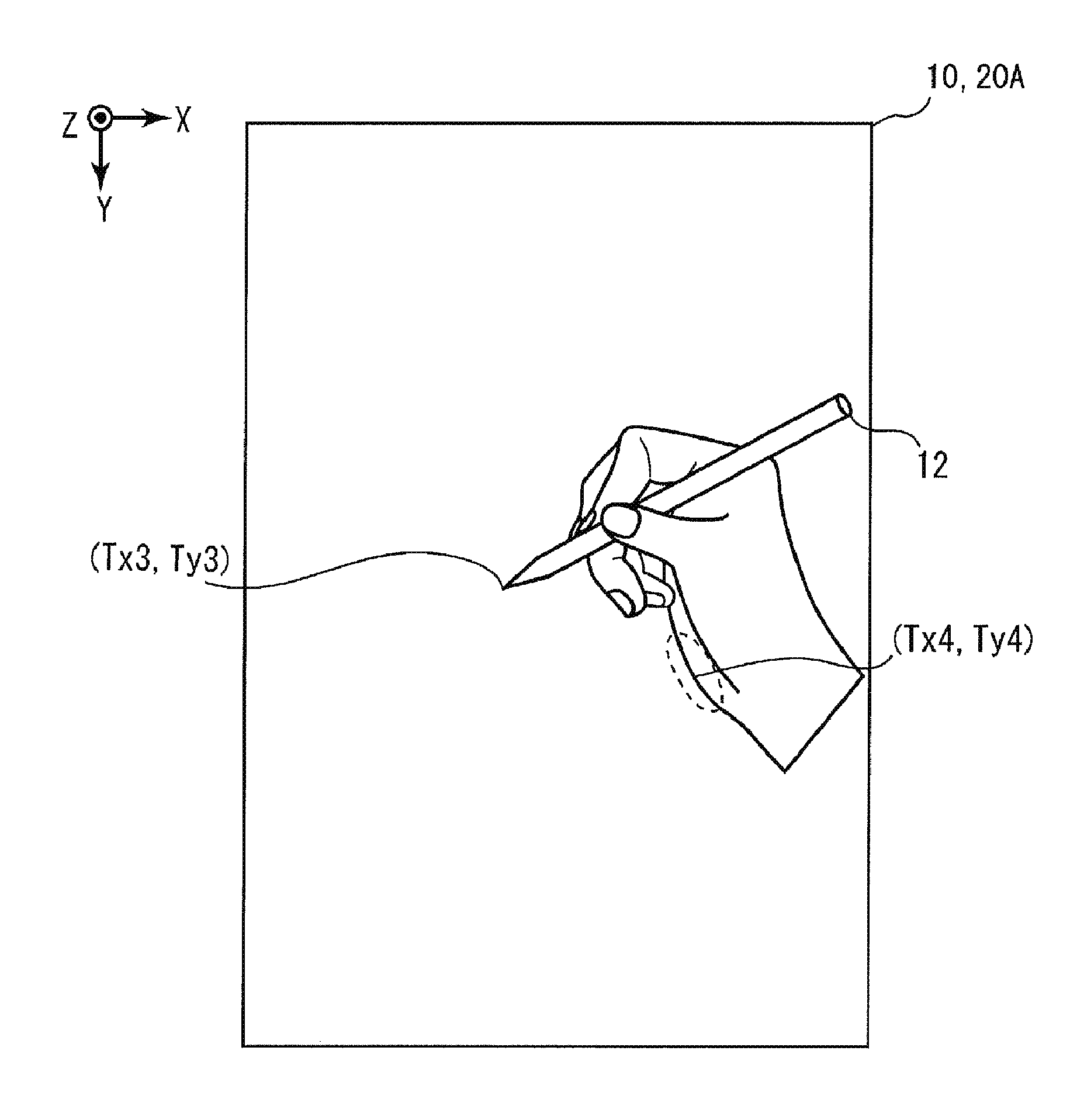
This is due to parallax occurring in the touch panel display as a result of the distance between the display panel and the touch panel, and the like, resulting in a difference between an input target location and the input location input on the touch panel.
Thus, when the input location is corrected by a fixed amount regardless of which hand is gripping the touch pen, it is not possible to correct the input location to the location that the user desires.

Method used


Image

  • Display device
  • Display device
  • Display device

Examples


operation example

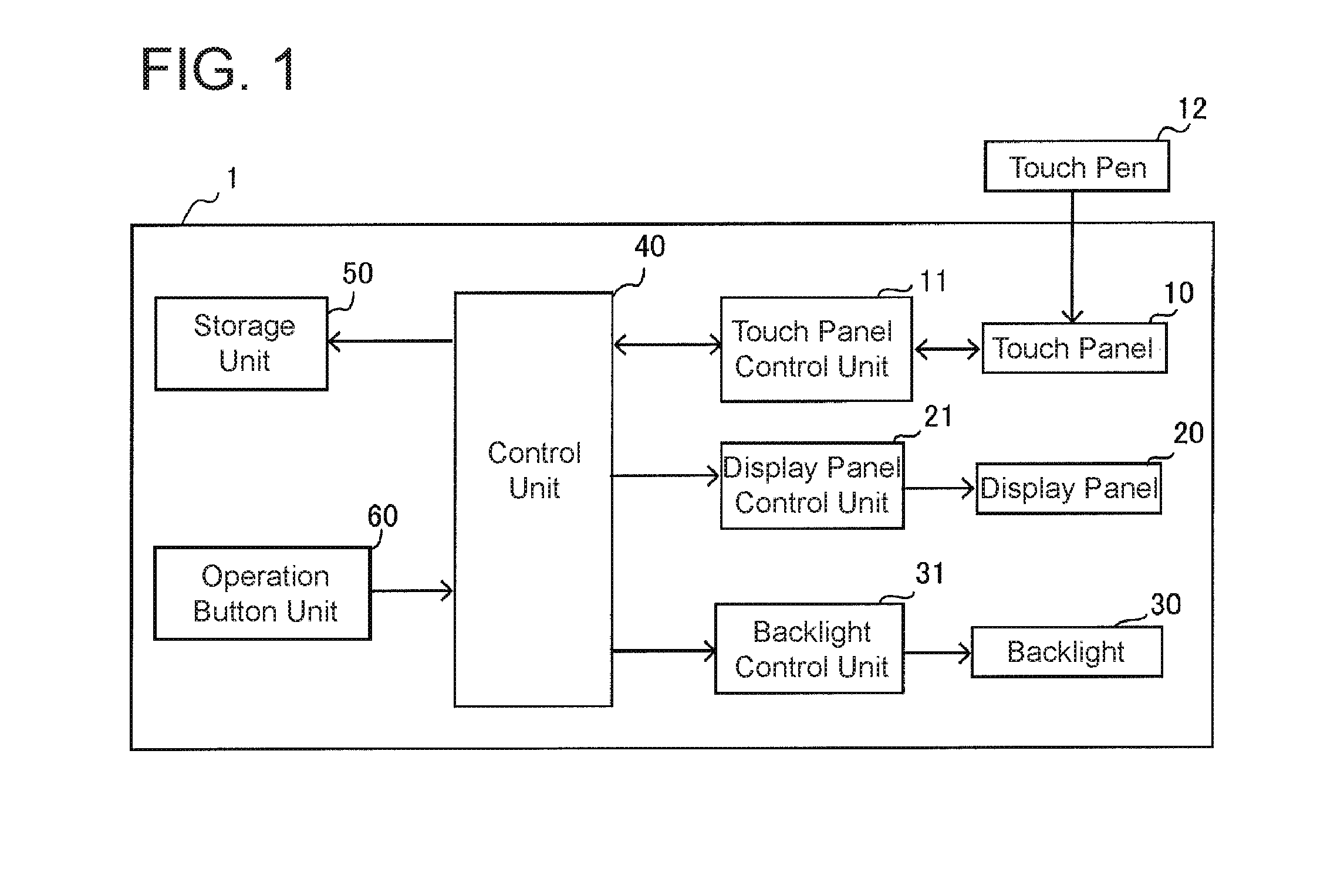
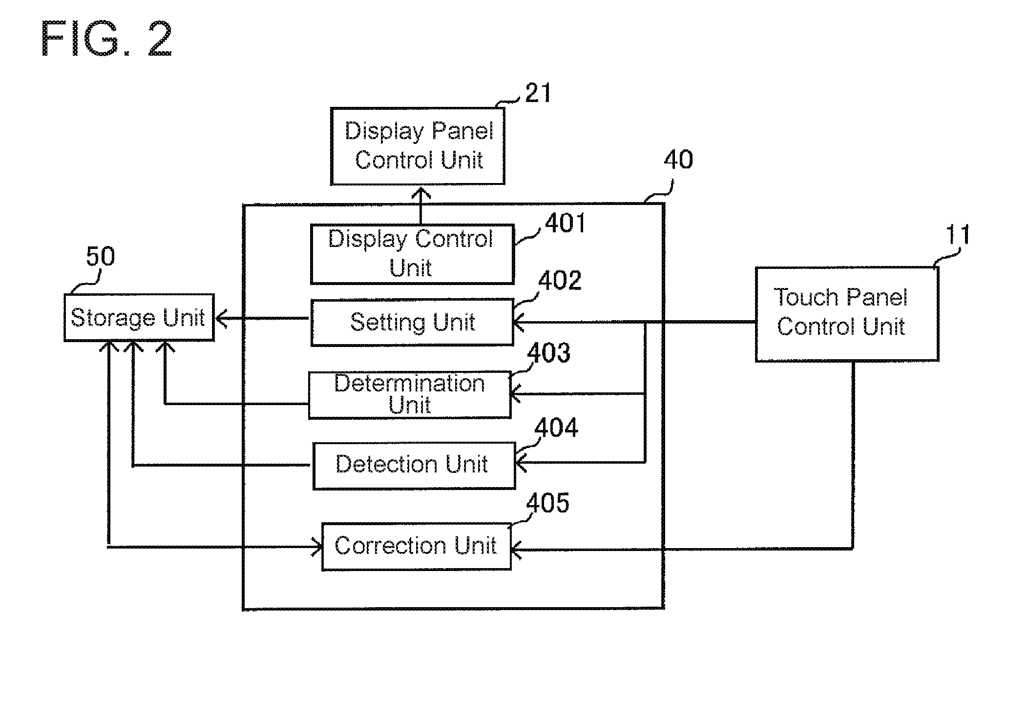
[0095]FIG. 7 is an operational flow chart that shows an operation example of the display device 1 of the present embodiment. When the control unit 40 receives an operation signal via the operation button unit 60 that the power button of the display device 1 has been turned ON (Step S11: Yes), the control unit 40, via the display panel control unit 21, displays the respective character images 200a, 200b shown in FIG. 3 in the display areas 201, 202 within the display area 20A of the display panel 20, and initiates calibration of the touch panel 10 (Step S12).

[0096]The user then performs an operation of tracing the character images 200a, 200b displayed in the display area 20A via the touch pen 12. The control unit 40, via the touch panel control unit 11, waits while displaying the character images 200a, 200b until the control unit 40 acquires the coordinates indicating the location contacted by the touch pen 12 (Step S13: No). After acquiring the coordinates indicating the position co...

modification examples

[0111]An embodiment of the present invention has been described above, but the above embodiment is a mere example of an implementation of the present invention. Thus, the present invention is not limited to the embodiment described above, and can be implemented by appropriately modifying the embodiment described above without departing from the spirit of the present invention. Next, modification examples of the present invention will be explained.

[0112](1) In the above-described embodiment, an example was used in which letters of the alphabet that were different from one another were displayed as the character images 200a, 200b. Japanese characters may be displayed as well, however. As shown in FIG. 8A, the Japanese hiragana character “” may be displayed as the character images 200a, 200b, for example. As shown in FIG. 8B, in such a case, the character image 200a shown in FIG. 8B is displayed in the display area 201 within the coordinate plane of the display area 20A such that porti...


PUM


Abstract

A display device includes: a display unit having a rectangular display area; a touch panel on the display unit; and a processor configured to perform the following: causing a character image to be displayed in a determination area located in a corner of the display area such that the character image contacts two sides of the determination area that border an exterior of the display area; determining whether a hand gripping the touch pen is a left hand or a right hand in accordance with input locations of the touch pen on the character image and a display location of the character image; detecting a shift amount in accordance with the input locations of the touch pen on the character image and the display location of the character image; and correcting an input location of the touch pen in the display area in accordance with the detected shift amount.

Description

TECHNICAL FIELD[0001]The present invention relates to a display device, and in particular, relates to a technology that corrects an input location by a touch pen in a display device equipped with a touch panel.BACKGROUND ART[0002]Mobile phones, tablet devices, and the like that include a touch panel display have recently become popular. There may be instances in a display device equipped with a touch panel in which, depending on the usage environment, there is a decrease in the accuracy in detecting an input location, and it may be necessary to perform calibration in order to correct the input location. As disclosed in Japanese Patent Application Laid Open Publication No. 2011-164742, for example, there is a method for performing calibration in which the display device displays an adjustment screen showing a cross mark or the like in order to adjust coordinates on the touch panel, and then adjusts the coordinates on the touch panel in accordance with the results of a contact operati...

Claims


Application Information

Patent Timeline
IPC IPC(8): G06F3/041G06F3/0354
CPCG06F3/0418G06F3/03545G06F3/0412G06F3/04883
Inventor KUGE, YOICHIHOSHIAI, NORIYUKI
Owner SHARP KK
Learn More