Power connection system

a power connection and power technology, applied in the direction of connection, electrical apparatus, coupling device connection, etc., can solve problems such as safety risks

Active Publication Date: 2013-12-19
CLUB CAR
View PDF30 Cites 26 Cited by
  • Summary
  • Abstract
  • Description
  • Claims
  • Application Information

AI Technical Summary

Benefits of technology

[0004]The receptacle of the present invention is comprised of a set of pins that provide the means for power to be fed to the charging system when connected to the live socket terminals within the plug. The receptacle also contains a permanent magnetic that provides the magnetic field to attract the iron core of the movable contact shuttle that is within the plug. The contact shuttle and iron core are spring-loaded to keep the contacts in the normally opened state, but are free to move within the plug housing when force is applied. The contact shuttle moves as the iron core is attracted to the permanent magnet during plug-in. The movable contacts close the circuit with the fixed contacts as a result of the shuttle movement towards the magnet. This contact closure then connects the AC input to the socket terminals. This connection within the plug connects power to the vehicle for its charging. This connection is only made when the plug and receptacle come together close enough that it provides protection for the user from the live pins and sockets within the plug / receptacle connection.

Problems solved by technology

During this power connection process, the user must grasp a live AC cord / plug set in order to make this connection, but there is an inherent safety risk when one grasps a live cord / plug set, especially in wet conditions.

Method used


Image

  • Power connection system
  • Power connection system
  • Power connection system

Examples


Embodiment Construction

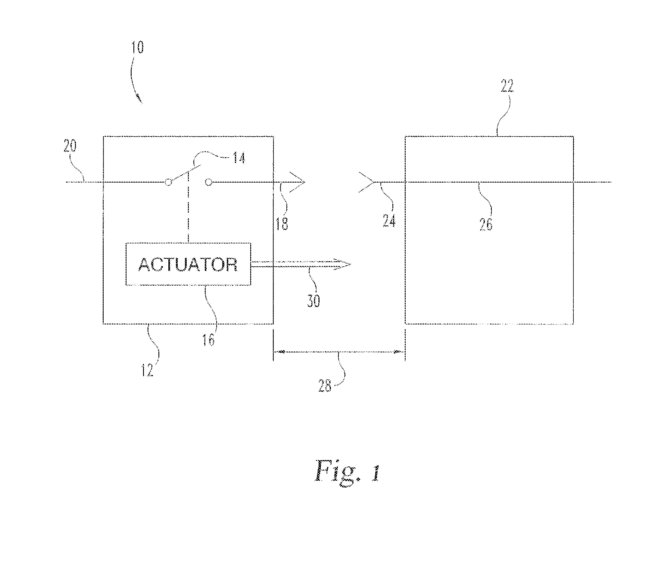
[0011]FIG. 1 is a block diagram of a connection system according to the preferred embodiment. In this embodiment, the connection system 10 includes a first connector 12 and a second connector 22.

[0012]The first connector 12 includes a normally-open switch 14 and an actuator 16. The actuator 16 is coupled to the normally open switch 14. Connector 12 includes a contact 18 and wiring 20 coupled to the switch 14. Connector 22 includes a contact 24 coupled to wiring 26. When the connector 12 and connector 22 are mated, the contact 18 is coupled to the contact 24. Accordingly, a connection can be made between wiring 20 and 26 when the switch 14 is closed.

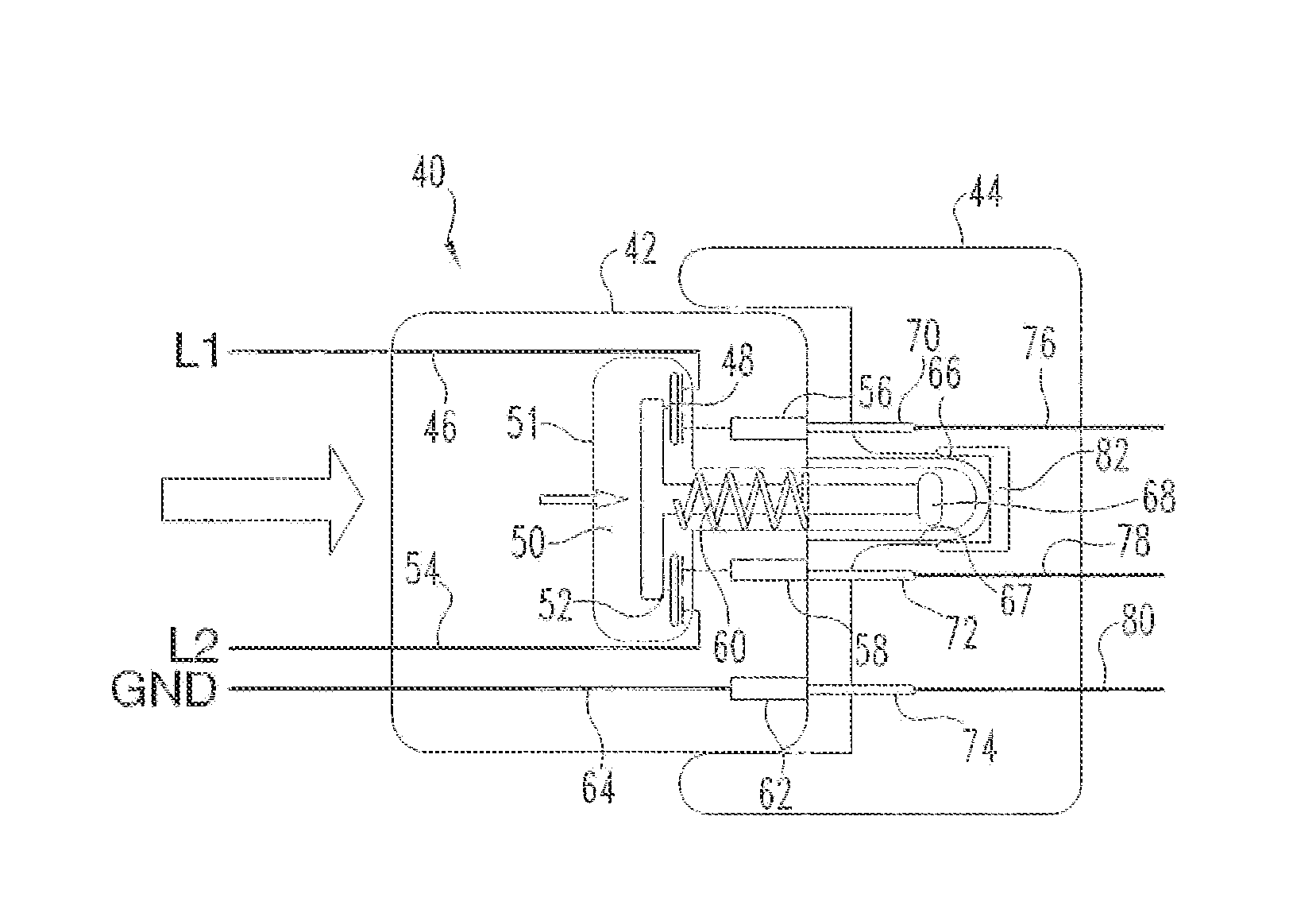
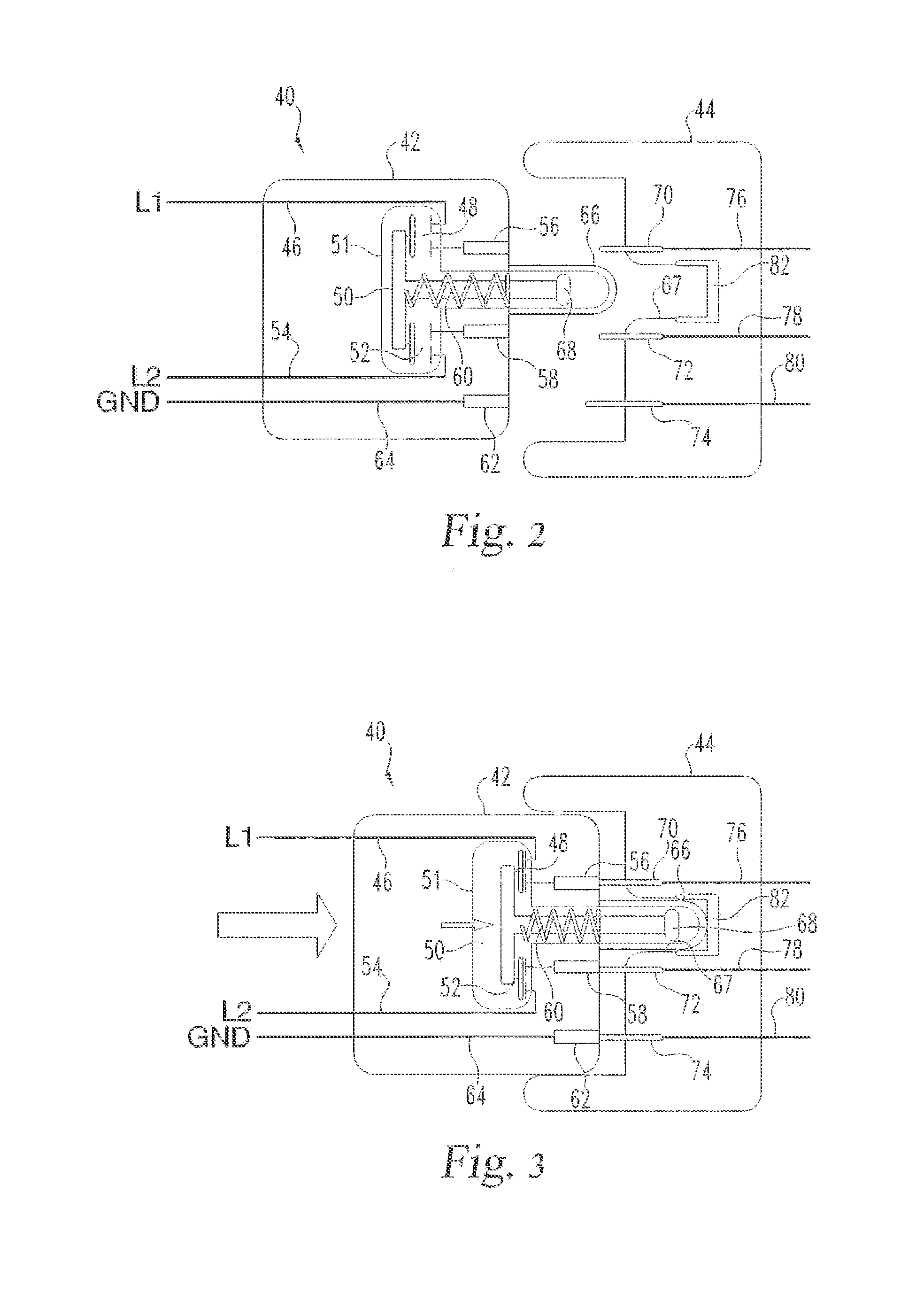
[0013]When the connector 12 and connector 22 are separated by less than a threshold distance 28 along the axis of insertion of the connectors 12 and 22, a force 30 between the actuator 16 and the connector 12 causes the actuator 16 to close the switch 14. As will be described in further detail below, the force 30 in the preferred embodime...


PUM


Abstract

An AC cord/plug is “dead” while disconnected and goes “live” only when connected. The plug has a set of spring-loaded, normally-open contacts, each having two sets of fixed contacts and a single set of movable contacts. The movable contacts are in a spring-loaded assembly that has an iron core opposite the contacts, and the fixed contacts are in a hermetically sealed compartment shielding them from the plug's exterior. The AC plug inputs (L1, L2) are connected to one set of the normally open, fixed contacts, and the plug's socket terminals are connected to the other set of normally opened, fixed contacts. In the unplugged state, the plug's socket contacts are electrically isolated from the L1 and L2 inputs. When plugged-in, the plug's socket terminals go “live” when a magnetic circuit closes between the plug and socket that causes the plug's spring-loaded assembly to move to close the contacts.

Description

[0001]The present invention relates to electric vehicles, generally, and more particularly to the power connections for recharging electric vehicles.BACKGROUND OF THE INVENTION[0002]Common to all electric vehicles is their need to have their traction battery packs recharged after use. The term “plug-in” in describing electric vehicles speaks directly to this universal requirement. This invention addresses the manner in which electric vehicles are plugged in for recharging. To enable an electric vehicle to replenish the traction battery system, the vehicle must be connected to a power source. For “plug-ins,” this typically involves connecting the power cord to an AC electrical service. During this power connection process, the user must grasp a live AC cord / plug set in order to make this connection, but there is an inherent safety risk when one grasps a live cord / plug set, especially in wet conditions.SUMMARY OF THE INVENTION[0003]The present invention provides a means for the AC cor...

Claims


Application Information

Patent Timeline
Patent Type & Authority Applications(United States)
IPC IPC(8): H01R13/713
CPCH01R13/713H01R13/635H01R13/7037
Inventor KING, RUSSELL W.SCHULT, DAVE NEAL
Owner CLUB CAR
Why Eureka
Try Eureka