Semiconductor switching element drive circuit

a switching element and drive circuit technology, applied in the direction of electronic switching, pulse technique, electrical apparatus, etc., can solve the problems of product cost and product size, and achieve the effect of suppressing its cost and siz

Active Publication Date: 2014-02-20
CALSONIC KANSEI CORP
View PDF9 Cites 11 Cited by
  • Summary
  • Abstract
  • Description
  • Claims
  • Application Information

AI Technical Summary

Benefits of technology

[0011]The semiconductor switching element drive circuit according to the invention has the threshold value change circuit that decreases the threshold value when the short protection circuit decreases the main current, and therefore it can surely prevent the semiconductor switching element from breakdown by using the action of the over current protection circuit even when the current value that is restricted by the short circuit protection circuit varies, suppressing its cost and size.

Problems solved by technology

In the conventional semiconductor switching element drive circuit, a problem, however, occurs in a product size and a product cost so that the reliability of the over current protection circuit can be ensured.

Method used


Image

  • Semiconductor switching element drive circuit
  • Semiconductor switching element drive circuit
  • Semiconductor switching element drive circuit

Examples


first embodiment

[0052]First, an entire construction of a semiconductor switching element drive circuit of a first embodiment will be described.

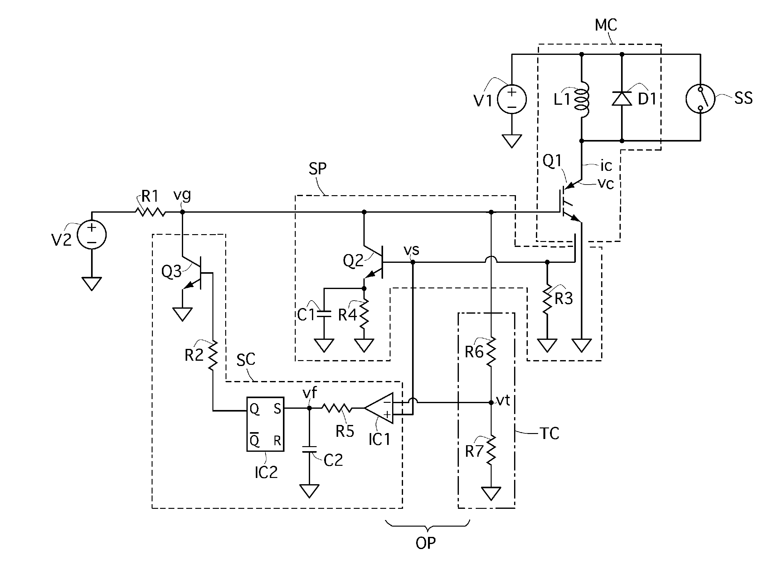
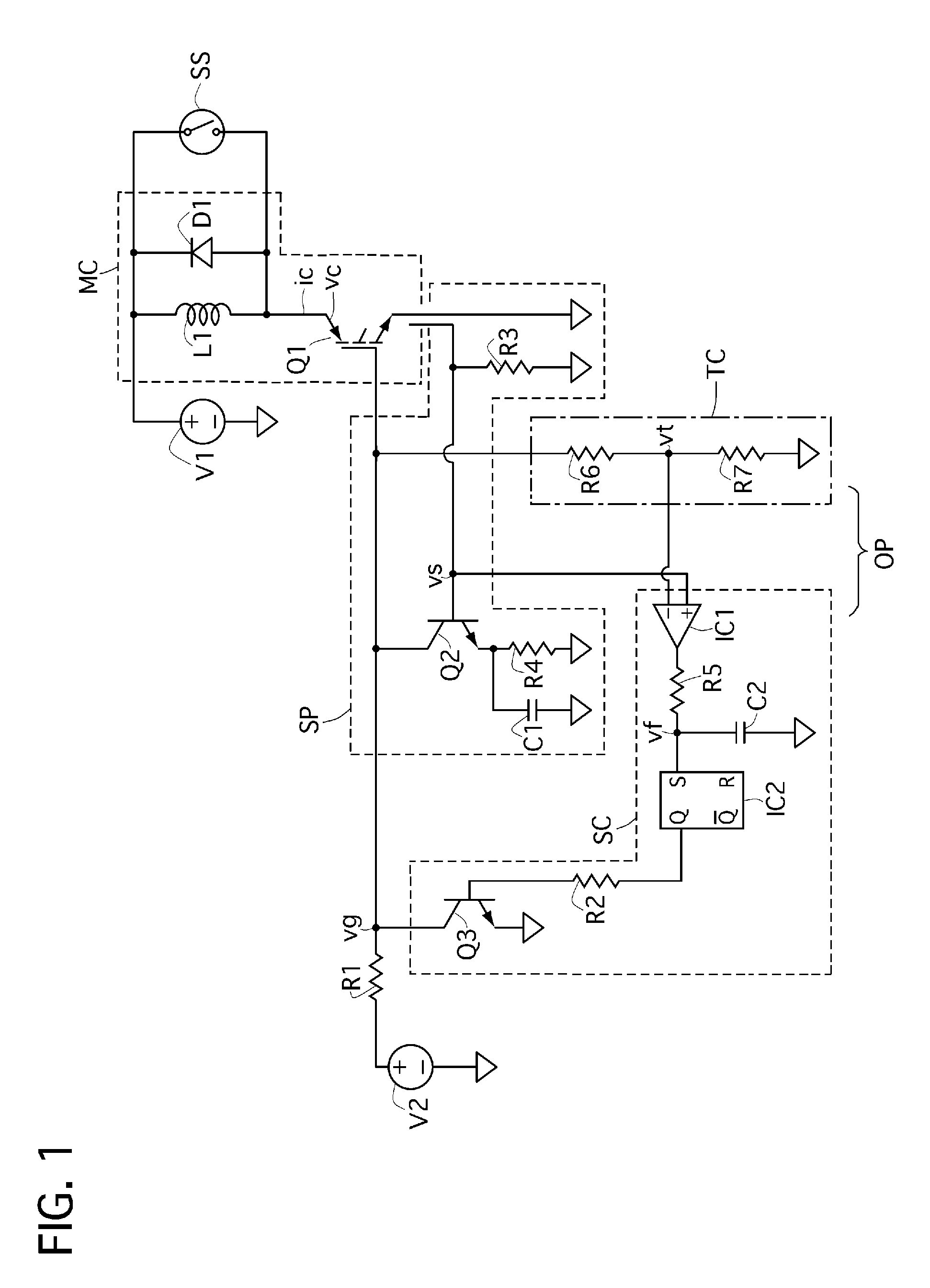
[0053]The semiconductor switching element drive circuit is used for a motor drive circuit to drive an electric vehicle, for example, employing a known technology using a three-phase alternating current motor in which each coil thereof is supplied with electric power for example. As shown in FIG. 1, the semiconductor switching element drive circuit of the first embodiment includes a circuit MC having motor coils and an inverter, a short circuit protection circuit SP, and an over current protection circuit OP provided with an over current threshold value voltage setting circuit TC and a switching circuit SC. Incidentally, the circuit MC in FIG. 1 uses a part of the motor and a part of a circuit of the inverter for a simulation, but it is essentially the same as those of the known technology.

[0054]It has a coil L1 expressing a coil of the motor, a feedback diod...

second embodiment

[0094]Next, a semiconductor switching element drive circuit of a second embodiment according to the present invention will be described with reference to FIGS. 4 to 6.

[0095]As shown in FIG. 4, the semiconductor switching element drive circuit of the second embodiment is different from the first embodiment in a circuit for setting masking time used in the switching circuit SS of the over current protection circuit OP.

[0096]That is, the over current threshold value voltage vt obtained by volt-dividing the gate voltage vg by using the resistances R6 and R7 in the over current threshold value setting circuit TC is imposed to the reverse input terminal of the first comparator IC1 similarly to the first embodiment, also being imposed to a non-reverse input terminal of a second comparator IC3 that is arranged parallel to the first comparator IC1. In addition, the sense voltage vs is inputted to the non-reverse input terminal of the first comparator IC1 similarly to the first embodiment, wh...

third embodiment

[0105]Next, a semiconductor switching element drive circuit of a third embodiment according to the present invention will be described with reference to FIGS. 7 to 9.

[0106]As shown in FIG. 7, the semiconductor switching element drive circuit of a third embodiment is different from the first embodiment in the over current threshold value setting circuit TC.

[0107]That is, in the semiconductor switching element drive circuit of the third embodiment, an intermediate portion between the resistance R6 and the resistance R7 is connected to a non-reverse input terminal of a third comparator IC4, and a reverse input terminal thereof is connected to a power supply V5, being imposed with a certain voltage. The output terminal of the third comparator IC4 is connected to an intermediate portion between the resistances R9 and R10 arranged in series. The other end portion f the resistance R10 is grounded, while the other end portion of the resistance R9 is connected to a power supply V6 through a ...


PUM


Abstract

A semiconductor switching element drive circuit includes a semiconductor that passes main current between first and second terminals when voltage is imposed to a gate terminal, and an over current protection circuit that decreases the main current when the main current is judged to become over current for a certain period when exceeding a predetermined current value when current value or voltage value proportional to an amplitude of the main current exceeds a threshold value. The circuit also includes a short circuit protection circuit that decreases gate voltage imposed to the gate terminal earlier than a fall of the main current produced by the over current protection circuit when the main current becomes larger than the over current in a period shorter than the certain period, and a threshold value change circuit that decreases a threshold value when the short circuit protection circuit decreases the main current.

Description

TECHNICAL FIELD[0001]The present invention relates to a semiconductor switching element drive circuit that is capable of preventing a semiconductor switching element from breakdown in a case where over current runs through the terminals of the element or in a case where a load such as an electric motor becomes to be in a short circuit state while the element is driven.BACKGROUND OF THE INVENTION[0002]A conventional semiconductor switching element drive circuit is known in the Patent document 1 shown below. This conventional semiconductor switching element drive device includes a semiconductor switching element, an over current protection circuit, and an over current restriction circuit (a short circuit protection circuit). The switching element passes main current between a first terminal and a second terminal thereof when current is imposed to a gate terminal thereof. The over current protection circuit decreases the main current at a first inclination in a case where the over curr...

Claims


Application Information

Patent Timeline
Patent Type & Authority Applications(United States)
IPC IPC(8): H02H9/02
CPCH02H9/025H03K17/0828
Inventor KIKUCHI, YOSHIYUKI
Owner CALSONIC KANSEI CORP
Why Eureka
Try Eureka