Aircraft lavatory

a technology for lavatory and aircraft, which is applied in the field of lavatory, can solve the problems of increasing the number of lavatory (toilets) to be provided, and the limited space on the aircraft must be utilized efficiently, so as to reduce the cost and time of installation and increase the storage space

Active Publication Date: 2018-05-03
JAMCO
View PDF9 Cites 0 Cited by
  • Summary
  • Abstract
  • Description
  • Claims
  • Application Information

AI Technical Summary

Benefits of technology

[0013]The present invention provides an aircraft lavatory unit capable of suppressing cost and time for installing a lavatory unit and an ascending / descending unit.
[0014]Further, in a case where a staircase is used as the ascending / descending unit, an additional storage space can be secured.

Problems solved by technology

Passenger aircrafts are designed with the aim to secure as much passenger seats as possible, in order to allow many passengers to be on board the aircrafts for commercial reasons, but increasing the number of passenger seats leads to increasing the number of lavatories (toilets) to be provided, so that limited spaces on the aircrafts must be utilized efficiently.

Method used


Image

  • Aircraft lavatory
  • Aircraft lavatory

Examples


Embodiment Construction

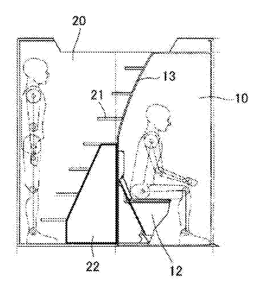
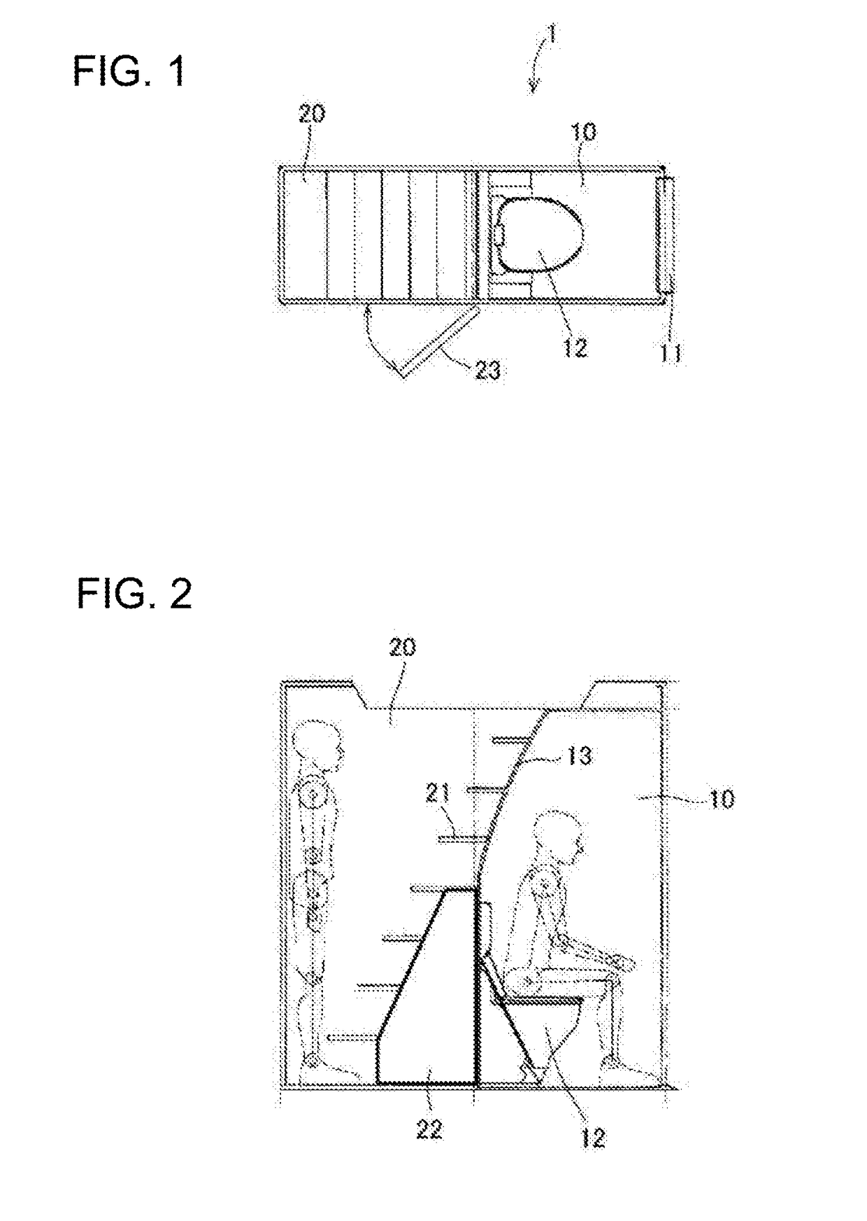
[0017]FIG. 1 is a plan view illustrating an outline of an aircraft lavatory unit according to the present invention. FIG. 2 is a side view of the aircraft lavatory unit illustrated in FIG. 1.

[0018]In FIG. 1, a ceiling member of the lavatory unit is not shown, and in FIG. 2, a side wall member of the lavatory unit is not shown.

[0019]As illustrated in FIGS. 1 and 2, an aircraft lavatory unit 1 according to the present invention is formed by integrally assembling a lavatory area 10 and an ascending / descending area 20.

[0020]A door 11 for entering into and exiting from the lavatory area 10 and a toilet unit 12 are provided in the lavatory area 10.

[0021]As illustrated in FIG. 2, the toilet unit 12 is arranged so that a person faces the door 11 when he or she seats thereon, and a wall surface 13 positioned on a rear side of the toilet unit 12 is designed to overhang further toward the door 11 at positions closer to a ceiling.

[0022]According to this arrangement, the width of the lavatory un...


PUM


Abstract

In providing an aircraft lavatory unit capable of suppressing cost and time for installation in a case where a lavatory unit and an ascending / descending unit are to be installed on the aircraft, the present invention provides an aircraft lavatory unit in which a lavatory area and an ascending / descending area are integrally formed, wherein an ascending / descending mechanism which connects to an upper floor or a ceiling space of the aircraft lavatory unit inside the ascending / descending area is provided on a wall surface dividing the lavatory area and the ascending / descending area.

Description

TECHNICAL FIELD[0001]The present invention relates to a lavatory (toilet) applied to a passenger aircraft.BACKGROUND ART[0002]Passenger aircrafts are designed with the aim to secure as much passenger seats as possible, in order to allow many passengers to be on board the aircrafts for commercial reasons, but increasing the number of passenger seats leads to increasing the number of lavatories (toilets) to be provided, so that limited spaces on the aircrafts must be utilized efficiently.[0003]In response to such demands, a configuration is known where an interior of an aircraft is divided into an upper deck and a lower deck, wherein cabin modules are arranged on each of the upper deck and the lower deck, and the upper deck and the lower deck are designed to be connected to a staircase that is disposed separately, through which passengers are enabled to move up and down (refer to Patent Literature 1).[0004]Similarly, a method is known where a toilet facility is arranged in a space bel...

Claims


Application Information

Patent Timeline
Patent Type & Authority Applications(United States)
IPC IPC(8): B64D11/02
CPCB64D11/02B64C2211/00B64D2011/0046
Inventor OOI, KOUICHITSUTSUI, YOSHIHISA
Owner JAMCO
Why Eureka
Try Eureka