[0038]In the figures, the elements that are identical or equivalent will bear the same reference signs.
DESCRIPTION OF THE PREFERRED EMBODIMENT
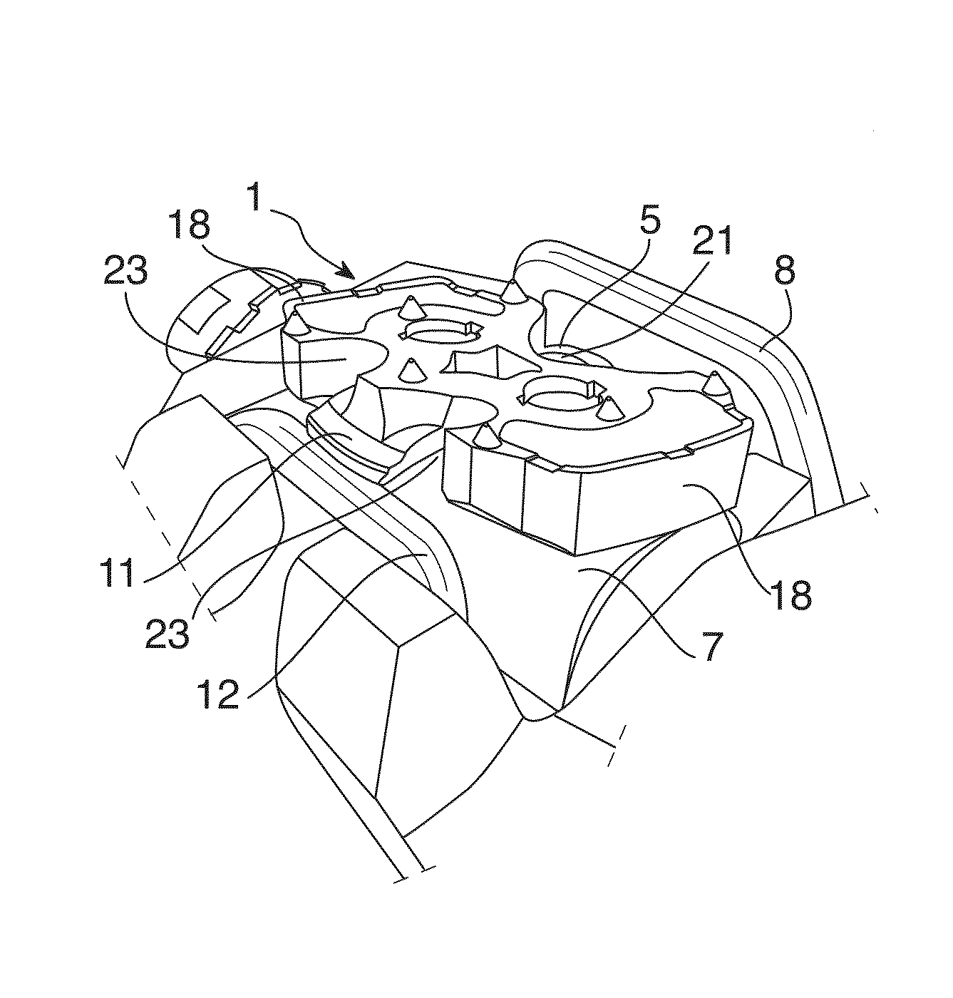
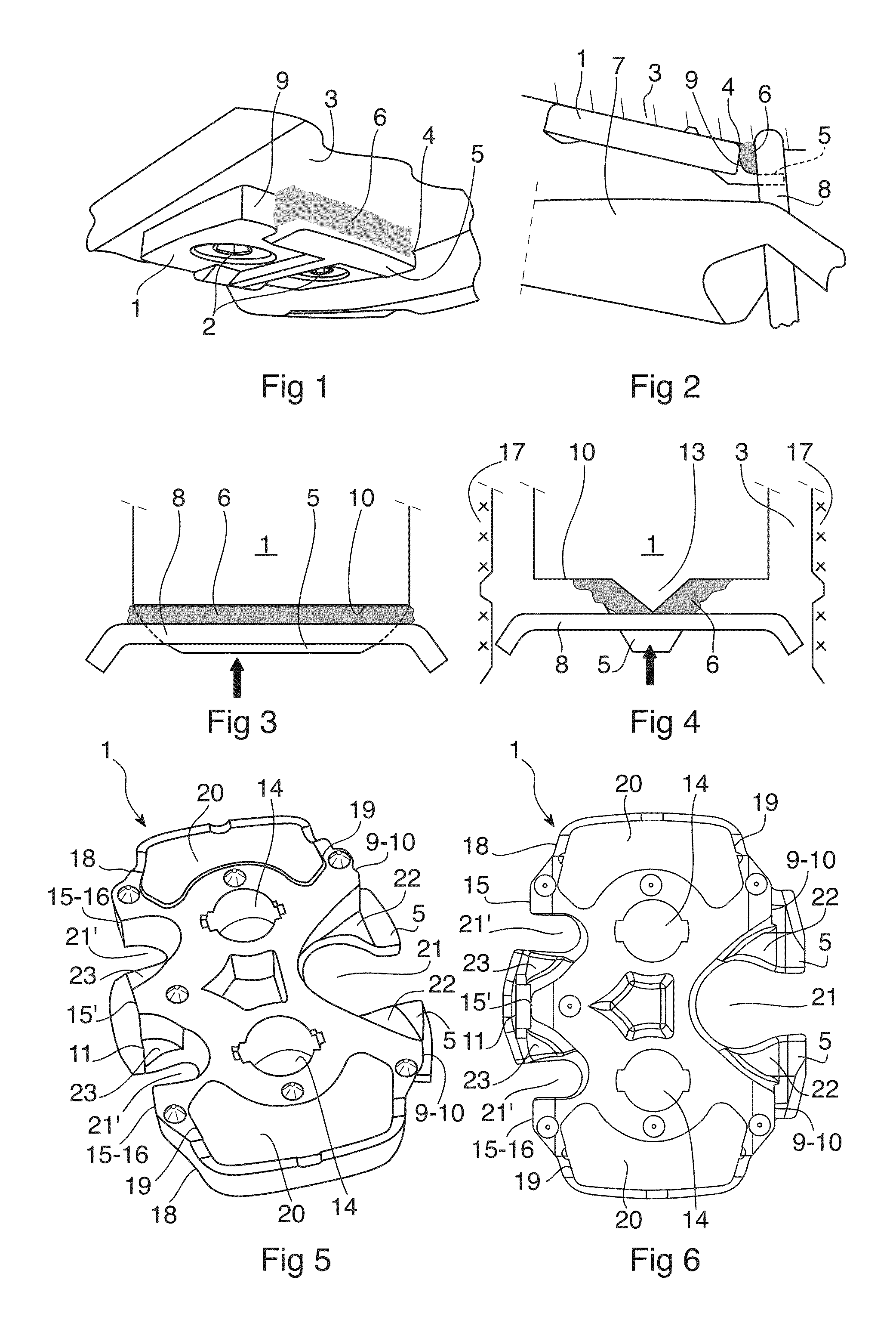
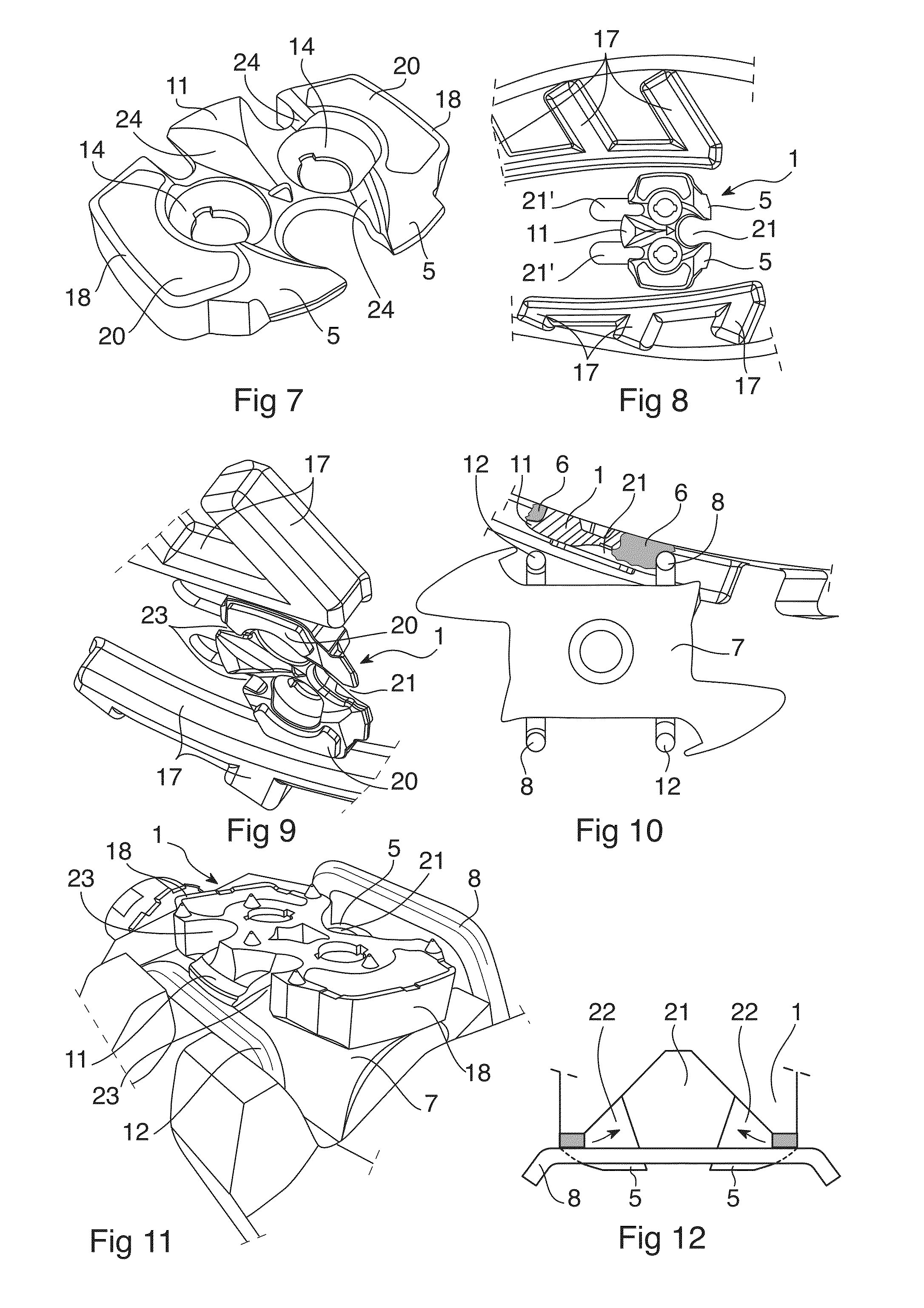
[0039]The link plate 1 according to the invention illustrated in FIGS. 1 to 12 conventionally comprises through holes 14 for fastening the link plate under the sole 3 of the cyclist's shoe (not represented), a front attachment member 5 suitable for cooperating with a front attachment member 8 of an automatic cycle pedal 7, and a rear attachment member 11 suitable for cooperating with a rear attachment member 12 of the pedal. In its position engaged on the pedal, the link plate 1 is gripped between the front and rear attachment members 8, 12 of the pedal which bear against a front gripping surface 9 and a rear gripping surface 15 provided on the front 10, respectively rear 15, rim of the plate 1.
[0040]The sole 3 is also provided with rows of crampons 17 positioned on either side of the link plate 1 so that the latter is practically integrated in the sole.
[0041]Furthermore, the link plate according to the invention illustrated in the figures comprises, on two opposite side wings 18, a respective recess 19 for receiving an elastic block 20 which protrudes slightly downward to serve as a bearing surface for walking, complementing the crampons 17, when the cyclist has taken the shoe off the pedal.
[0042]According to the invention, at least one of the front and rear gripping surfaces 10, 15 of the link plate 1 is divided into a plurality of parts by at least one notch 21 forming an opening for evacuating external matter 6 likely to penetrate into an interstice 4 formed between the sole 3 of the shoe and the front and rear attachment members 5, 11 of the plate. The evacuation opening-forming notch 21 is a through notch extending through the entire thickness of the link plate from a top face to a bottom face thereof, allowing the mud to pass through to the bottom face for its evacuation to the pedal.
[0043]This dividing up of the front and/or rear gripping surface 10, 15 has the direct consequence of causing this surface to be reduced, which will firstly result in a reduction of the surface on the rim 10 and/or 15 against which the mud 6 can be stressed by the corresponding attachment member of the pedal, and secondly in an increase in the pressure that it exerts on the accumulated mud (see FIG. 12). The mud 6 will thus be forced toward the evacuation opening-forming notch 21.
[0044]In the example illustrated in the figures, a single evacuation opening-forming notch 21 is placed at the center of the front rim 10 of the plate so as to divide the front attachment member 5 into two parts.
[0045]The link plate 1 has, in the place of the front attachment member 5, a part with contour directed inward so that the face of each part of the front attachment member that has to face toward the sole of the shoe forms therewith an evacuation channel 22 communicating with the central evacuation opening-forming notch 21.
[0046]Also in the example illustrated, two evacuation opening-forming notches 21′ which are positioned on either side of the rear attachment member 11 of the plate divide the rear gripping surface into three parts.
[0047]The link plate 1 here has, on either side of a central gripping surface 15′, in the place of the rear attachment member 11, a part with contour in extension of the contour of the respective notch 21′ which is linked to the central gripping surface 15′ so that the face of a part of the rear attachment member 11 that has to face toward the sole 3 of the shoe and positioned on either side of said central gripping surface forms, with the sole of the shoe, an evacuation channel 23 communicating with a respective notch 21′.
[0048]The configuration described with a front central notch 21 and two rear side notches 21′ seems to be an optimum solution for the evacuation of the mud which would otherwise be captive and compacted in the interstice 4.
[0049]It is obvious that all the combinations can be envisaged without in any way departing from the framework of the invention.
[0050]Moreover, the link plate 1 is advantageously, on its face that has to face toward the pedal, provided, around each evacuation opening-forming notch 21, 21′, with a distribution depression 24 for distributing the mud which is expelled through the corresponding notch.
[0051]Advantageously, these distribution depressions 24 communicate with one another.
[0052]Finally, the bottom of each evacuation opening-forming notch 21, 21′ is rounded.
[0053]Obviously, the invention is not limited to the example illustrated and described, but can be applied to any link plate for an automatic pedal.