Surfboard Fin for Generating Surfboard Lift and Method of Use

a technology of surfboards and fins, applied in the field of surfboards, can solve the problems of generating turbulence, disrupting laminar flow, and creating turbulence, and achieve the effect of generating li

Inactive Publication Date: 2014-03-20
HILL MARK AARON +1
View PDF1 Cites 6 Cited by
  • Summary
  • Abstract
  • Description
  • Claims
  • Application Information

AI Technical Summary

Benefits of technology

[0012]In some embodiments, the second angular fin comprises at least two fin components, a first fin component and a second fin component, with a bend or elbow between first fin component and second fin component and a bend between first fin component and base member (as described above) wherein the first tin component extends downward from the second edge of the base at an angle of 17.99° from the substantially vertical, fin for a specified length and the second fin component extends downward at an angle of 72.10° until the second angular fin reaches and is attached to the substantially vertical fin. The angular design of the second angular fin and engagement to a second edge of base member and lower portion of the substantially vertical fin yields a box design in some embodiments. In some embodiments, the lead opening of the box is larger than the rear opening resulting in a Venturi effect.
[0013]In some embodiments, the second angular fin may be attached to the first substantially vertical fin at an angle to redirect water downward through the box design—thereby generating lift. To achieve this effect, in some embodiments, the second fin is attached at a 5° declined plane in relation to the plane of the water surface on which the surfboard rides.

Problems solved by technology

For example, turbulence may be created by high surface friction coefficients and disrupt desired laminar flow.
Cavitation may disrupt laminar flow and will also produce aquatic sounds as the bubbles collapse and return to solution.

Method used


Image

  • Surfboard Fin for Generating Surfboard Lift and Method of Use
  • Surfboard Fin for Generating Surfboard Lift and Method of Use
  • Surfboard Fin for Generating Surfboard Lift and Method of Use

Examples


Embodiment Construction

[0024]Further scope of applicability of the present invention will become apparent from the description of representative embodiments given herein. However, it should be understood that the description and specific examples, while indicating embodiments of the invention, are given by way of illustration only since various changes and modifications within the spirit and scope of the invention will become apparent to those skilled in the art.

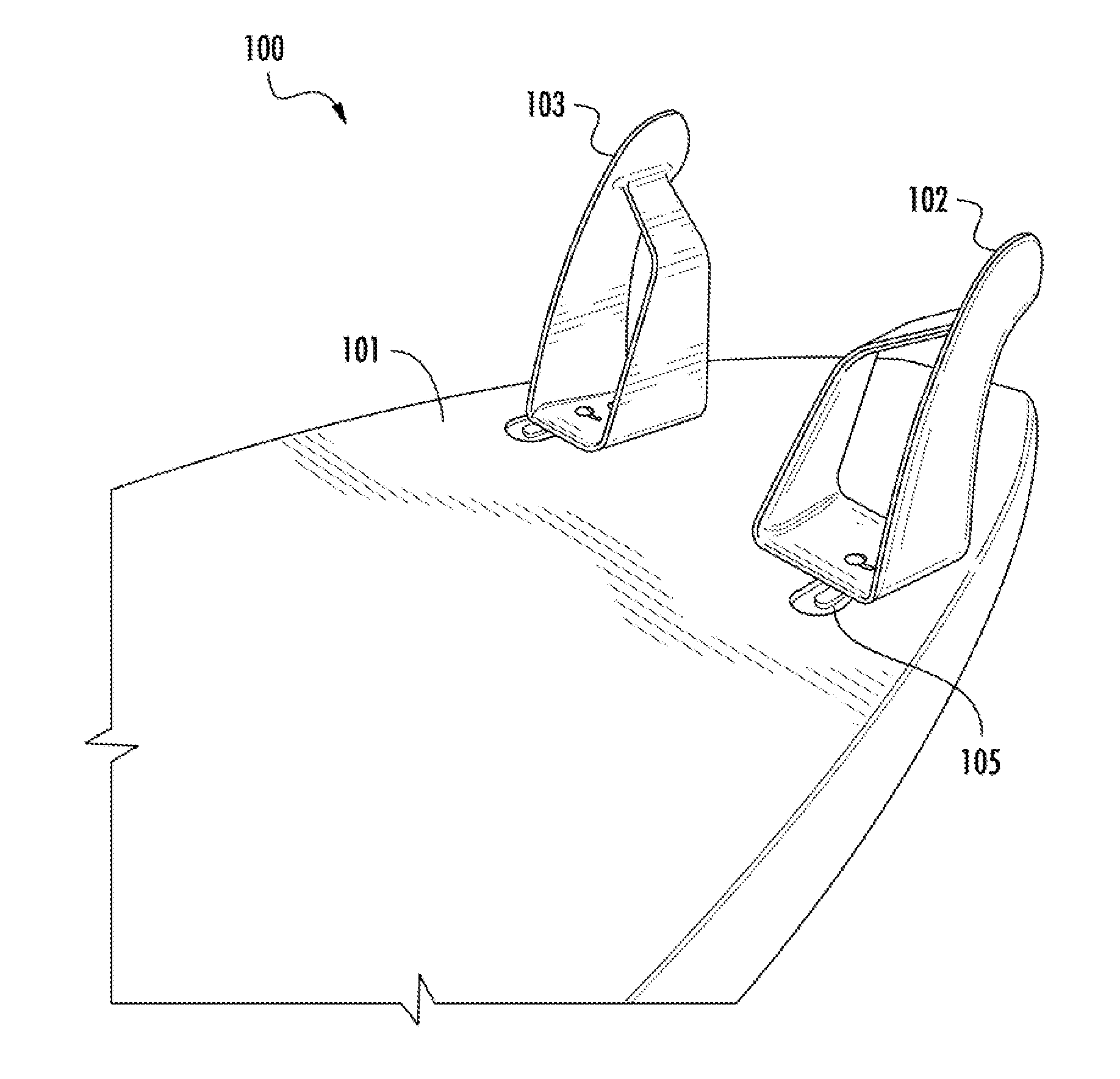
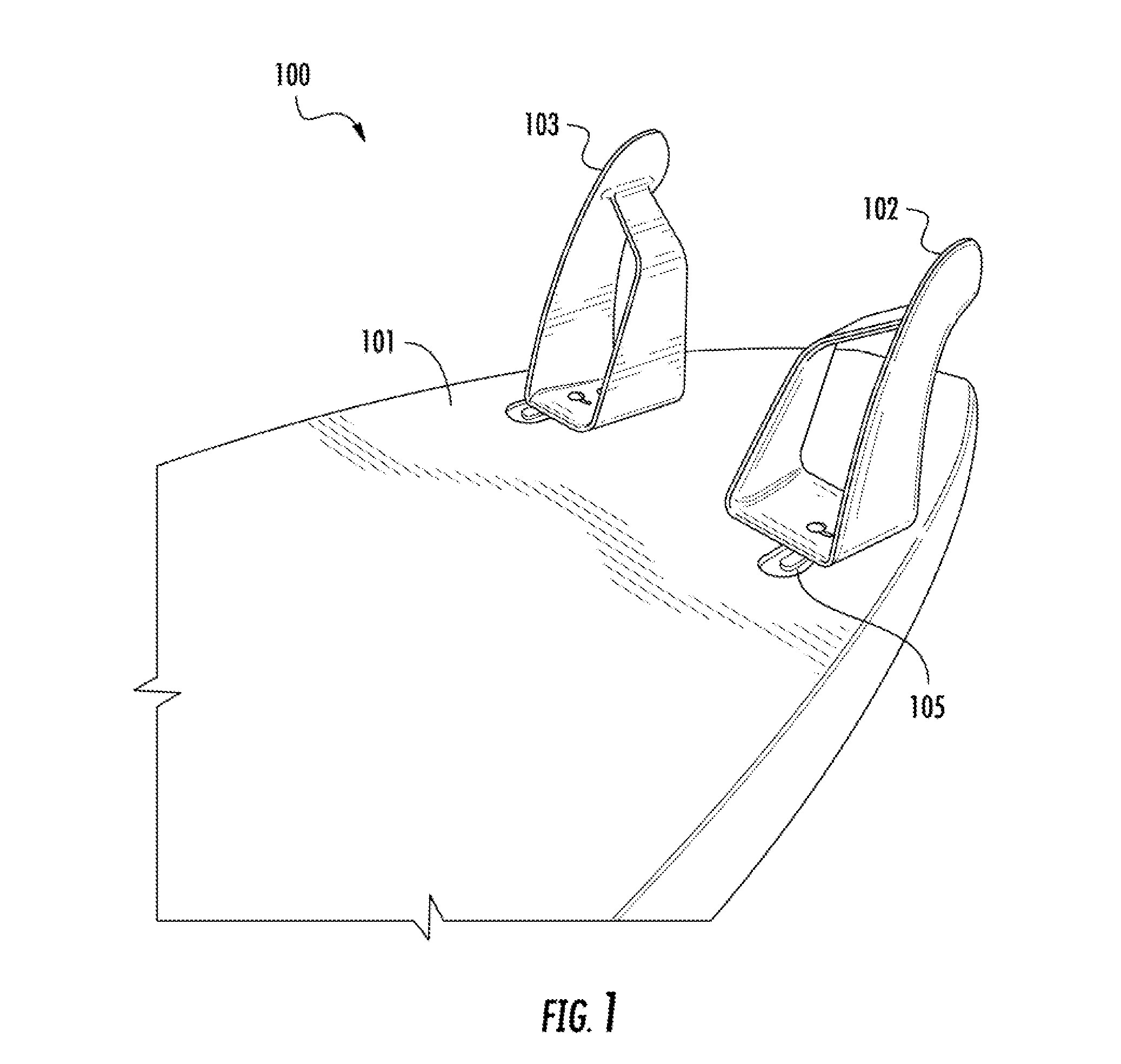
[0025]FIG. 1 is a perspective view 100 of the lifted fin apparatus from underneath a surfboard 101 with two lifted fin elements 102, 103 mounted to the bottom of the surfboard 100 at the rear. In this embodiment, lifted fin element 102 is designed to be affixed to the left side of a surfboard and lifted fin element 103 is designed to be affixed to the right side of a surfboard in accordance with the invention (the designations left and right are from the standpoint of a rider standing on the surfboard facing in the direction of travel). The embodi...


PUM


Abstract

The present invention relates to a lifted fin apparatus comprising one or more lifted fin elements with foiled tin components for a reduction of pressure and drag and an increase in surfboard lift as well as a method of achieving surfboard lift through, the use of said apparatus. Generally, the lifted fin apparatus comprises two or more lifted fin elements exhibiting a foil design on one or more of the fin surfaces. The individual fin elements may comprise a substantially vertical fin attached to a first edge of a base member and oriented at a substantially 90° angle in relation to the bottom surface of the surfboard or to the first edge of the base member. The fin elements may further comprise an angular fin mounted to a second edge of the base member at one end and the lower portion of the first, fin at the other end. In said embodiment, a bend or elbow is formed between a first fin component of angular fin and base member proximate the point of attachment at second edge of base member. Alternatively, the base member may not have a defined second edge representing the intersection between base member and a first fin component of angular fin, but rather the base member and the angular fin may be manufactured as a unitary structure with a bend or elbow between base member and a first fin component as described below.

Description

RELATED APPLICATIONS[0001]This application claims priority to U.S. Provisional Patent Application Ser. No. 61 / 701,715 filed Sep. 16, 2012. The disclosure of U.S. Provisional Patent Application 61 / 701,715 is incorporated by reference herein in its entirety.FIELD OF THE INVENTION[0002]The invention relates generally to surfboards and more particularly to hydrodynamic fins mounted underneath a surfboard and methods of using the same to achieve surfboard lift.BACKGROUND OF THE INVENTION[0003]Surfboards may generally be described as water planing devices used to ride waves. The term “surfboard” may include boogie boards, wind surfing boards, and other hulled craft which are maneuvered by shitting the weight borne by the craft relative to the craft's center of gravity. Surfboards may be constructed of various lengths, width, shapes and thicknesses. Initially, surfboards had a single vertical fin located along the centerline of the surfboard at the rear that provided directional stability....

Claims


Application Information

Patent Timeline
Patent Type & Authority Applications(United States)
IPC IPC(8): B63B35/79
CPCB63B1/248B63B35/7923B63B35/7926B63B35/79B63B32/62B63B32/66B63B32/64
Inventor HILL, MARK AARONHILL, ANDREW STEVEN
Owner HILL MARK AARON
Why Eureka
Try Eureka