Eureka AIR delivers breakthrough ideas for toughest innovation challenges, trusted by R&D personnel around the world.

Rail stabilizer for rail tie replacement

Active Publication Date: 2014-04-10
GOOD EARTH TOOLS
View PDF9 Cites 1 Cited by
  • Summary
  • Abstract
  • Description
  • Claims
  • Application Information

AI Technical Summary

Benefits of technology

This patent provides a method and apparatus for stabilizing railroad rails during tie replacement on a working bridge or trestle. The apparatus includes a stabilizer consisting of a rod with a pair of rail clamps and an expanding member. The expanding member is carried by the rod and is designed to engage a structure proximal to the rails, such as a railway bridge, to maintain the fixes rails in relation to each other and the structure, but allow them to move vertically relative to the structure. The method involves clamping the rail to the rod, abutting the rod against the structure to secure the rail, and raising the rail to remove and replace the tie. The technical effects of this invention are improved stability and safety during tie replacement on bridges or trestles, reduced risk of injury or damage to the rails, and improved efficiency in the process of replacing rails.

Problems solved by technology

It is time- and labor-consuming and if not carefully carried out, runs the risk of damaging the track by moving the rails “out of gage” (too far apart or close together), out of parallel alignment relative to one another and to the rail bed, or bending the rails.
Replacement of rail ties is particularly challenging on railway bridges or trestles because the bridge is often the only solid surrounding structure on which workers and equipment can stand.
It is expensive and time-consuming to bring in large work gangs and bridge work is a special operation due to its additional safety (fall protection) and structural requirements. n these operations, the need for rail stabilization is particularly acute.

Method used


Image

  • Rail stabilizer for rail tie replacement
  • Rail stabilizer for rail tie replacement

Examples


Embodiment Construction

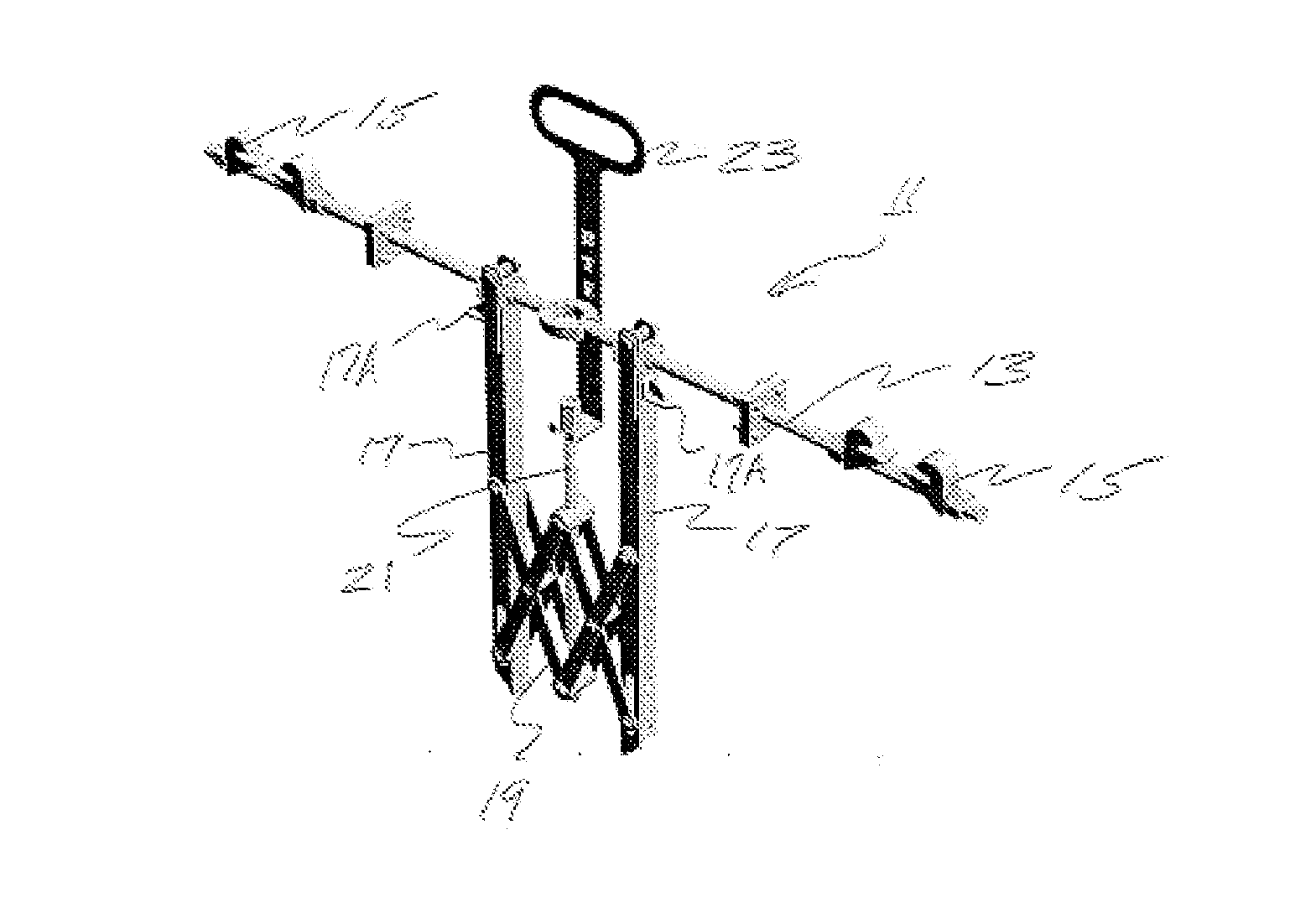
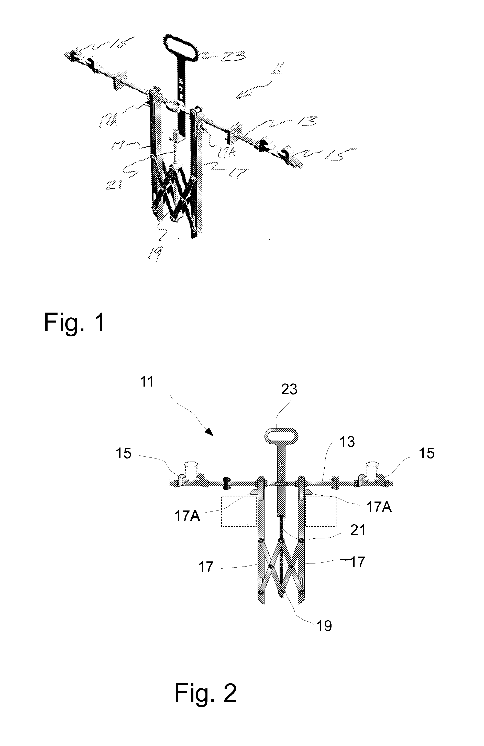
[0013]Referring now to the Figures and particularly to FIGS. 1 and 2, the rail tie stabilizer 11 according to the present invention will be described. Stabilizer 11 comprises a gage rod 13, which may be a length selected to correspond to the “gage” or width between rails. A pair of rail clamps 15 may be secured by threads and nuts on each end of gage rod 13. Rail clamps 15 are configured to securely and rigidly attach to railroad rails so that, in cooperation with gage rod 13, the rails are maintained spaced apart by the selected gage of the rail track. Rail clamps 15 may be electrically insulated to prevent interference with signals conducted by track.

[0014]A pair of shoes 17 may be slidably mounted at their upper ends to gage rod 13. Shoes 17 are movable along the length of gage rod 13 between expanded and collapsed positions and may be mounted to rod 13 using linear bearings and clevis pins for smooth operation and easy disassembly. A scissor mechanism 19 may be arranged between ...


PUM


Abstract

A stabilizer is disclosed for use in stabilizing and maintaining the spacing between a pair of railway rails during rail tie replacement. The stabilizer comprises a rod having a length and a pair of ends. A pair of rail clamps is carried by the rod, and each clamp is configured to engage one of the rails and secure the rail relative to the rod. An expanding member is carried by the rod and configured to selectively expand along the length of the rod between its ends to engage a structure proximal to the rails, wherein, upon engagement of the rails by the rail clamps and the expanding member with the structure, the rails are maintained in substantially fixed relationship to each other and to the structure, but are free to be moved vertically relative to the structure.

Description

TECHNICAL FIELD[0001]The present invention relates to methods and apparatus for stabilizing railway rails during railway repairs. More specifically, the present invention relates to methods and apparatus for maintaining the position of railway rails relative to one another and to an underlying structure while rail ties are being replaced, particularly on railway bridges.BACKGROUND OF THE INVENTION[0002]Replacement of rail ties is among the most common railroad or railway repairs. It is time- and labor-consuming and if not carefully carried out, runs the risk of damaging the track by moving the rails “out of gage” (too far apart or close together), out of parallel alignment relative to one another and to the rail bed, or bending the rails. Automated equipment exists for replacing rail ties that uses jigs and fixtures to stabilize the rails while old ties are removed and new ties driven in.[0003]Replacement of rail ties is particularly challenging on railway bridges or trestles becaus...

Claims


Application Information

Patent Timeline
IPC IPC(8): E01B29/09
CPCE01B26/00E01B29/10E01B29/16E01B29/04E01B31/00
Inventor WEYAND, MATTHEW ROGER
Owner GOOD EARTH TOOLS
Why Eureka
Eureka Blog
Learn More