
Auxiliary device for maintaining a screw upright

Inactive Publication Date: 2014-06-19
SCIENBIZIP CONSULTINGSHENZHENCO
View PDF4 Cites 0 Cited by
  • Summary
  • Abstract
  • Description
  • Claims
  • Application Information

AI Technical Summary

Benefits of technology

The patent is about a tool that helps keep a screw upright before it is turned and engaged in a hole. The "technical effect" is that this tool makes it easier and more accurate to install screws in holes.

Problems solved by technology

In manufacturing such tablet computers, it is found that the magnet may attract a screw that is ready to be screwed into two components of the tablet computer, and cause the screw to deflect.
The threaded hole of the two components may be damaged if the deflected screw is then turned by an electric screwdriver.

Method used


Image

  • Auxiliary device for maintaining a screw upright
  • Auxiliary device for maintaining a screw upright
  • Auxiliary device for maintaining a screw upright

Examples


Embodiment Construction

[0010]Embodiments of the present disclosure will be described with reference to the accompanying drawings.

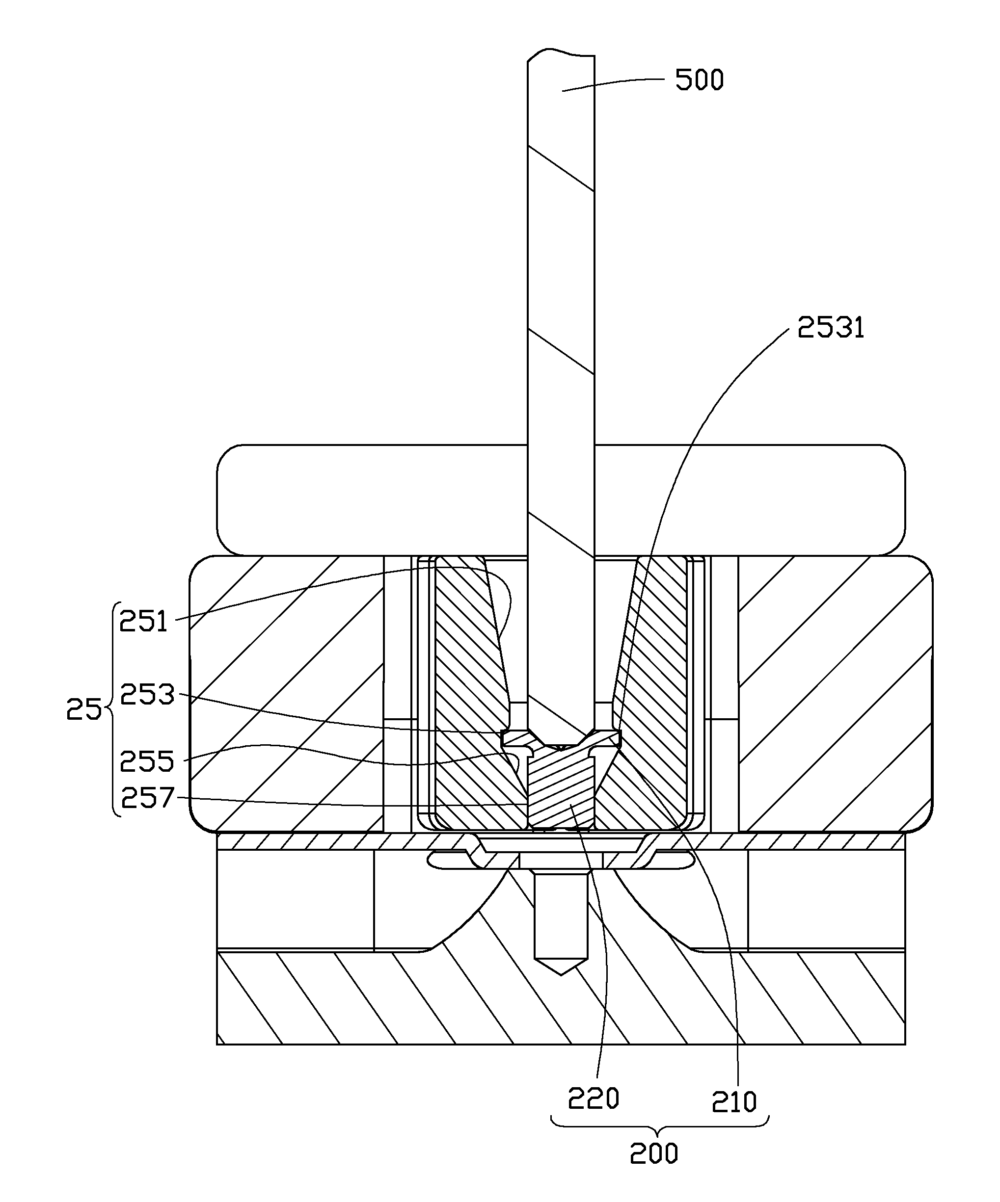
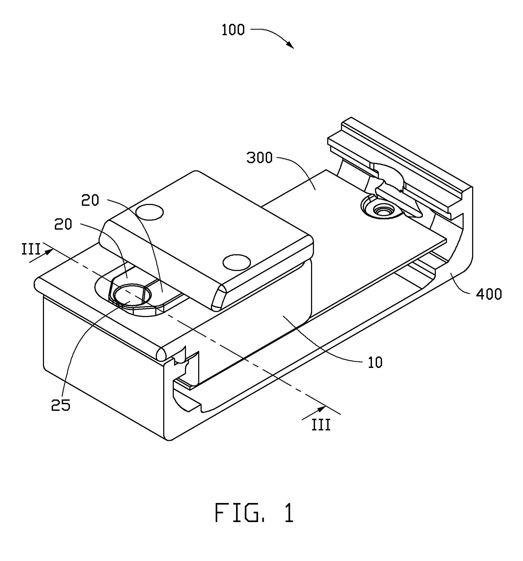
[0011]Referring to FIGS. 1-3, a metallic screw 200 connects a first workpiece 300 to a second workpiece 400. The second workpiece 400 includes a magnet. When the screw 200 is initially placed on the workpiece 400 and aligned with either of two threaded holes 410 of the workpiece 400, it is found that the magnet may cause the screw 200 to deflect. When this happens, the subsequent turning of the screw 200 by an electric screwdriver is liable to be problematic. An auxiliary device 100 for maintaining the screw 200 upright will now be described in detail.

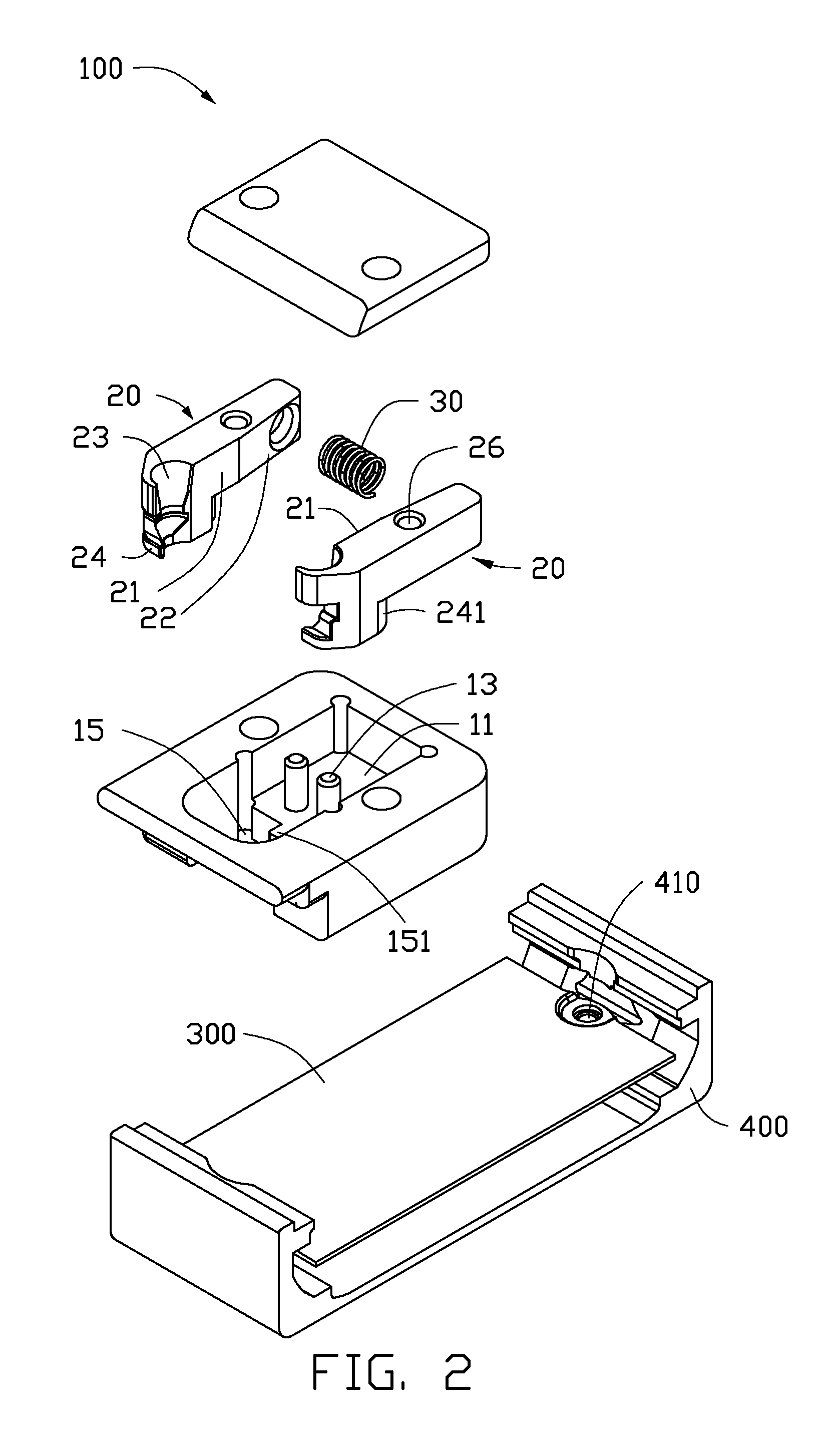
[0012]The auxiliary device 100 includes a base 10, and two rotatable arms 20 rotatably connected to the base 10. An elastic member 30 (e.g., a coil spring) is arranged between and applies a pushing force to the two rotatable arms 20, and thereby the two rotatable arms 20 are normally biasedly in contact with each other. In the embo...


PUM


Abstract

An auxiliary device includes a base, two rotatable arms, and an elastic member. The two arms are rotatably connected to the base and each includes a mating surface that defines a recess. The recesses of the two arms cooperatively form a through hole when the mating surface is in contact with each other. The through hole includes, from top to bottom, a first tapered hole portion, an annular groove, a second tapered hole portion, and a round hole portion. The annular groove is used to receive a head of a screw, and the round hole portion has a lateral surface is used to contact a shank of the screw to keep the screw upright. The elastic member is arranged between the two rotatable arms and applies a pushing force to the two rotatable arms.

Description

BACKGROUND[0001]1. Technical Field[0002]The present disclosure relates to an auxiliary device for maintaining a screw upright prior to the screw being turned and engaged in a hole.[0003]2. Description of Related Art[0004]Some tablet computers include a magnet for attracting an external protective cover. In manufacturing such tablet computers, it is found that the magnet may attract a screw that is ready to be screwed into two components of the tablet computer, and cause the screw to deflect. The threaded hole of the two components may be damaged if the deflected screw is then turned by an electric screwdriver.BRIEF DESCRIPTION OF THE DRAWINGS[0005]Many aspects of the embodiments can be better understood with reference to the following drawings. The components in the drawings are not necessarily drawn to scale, the emphasis instead being placed upon clearly illustrating the principles of the present disclosure. Moreover, in the drawings, like reference numerals designate correspondin...

Claims


Application Information

Patent Timeline
IPC IPC(8): B25B23/10
CPCB25B23/10B23P19/006
Inventor LU, LI-CHINXIANG, JIAN-HUA
Owner SCIENBIZIP CONSULTINGSHENZHENCO
Learn More