

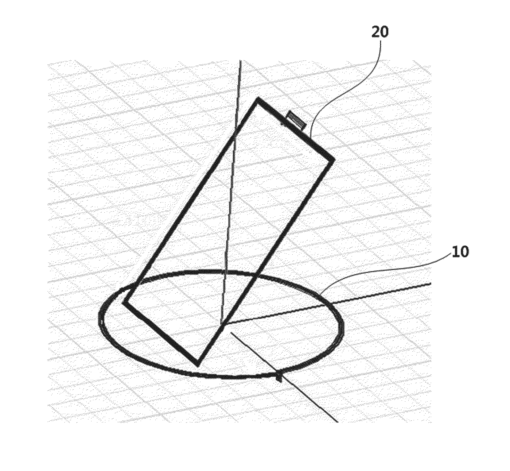
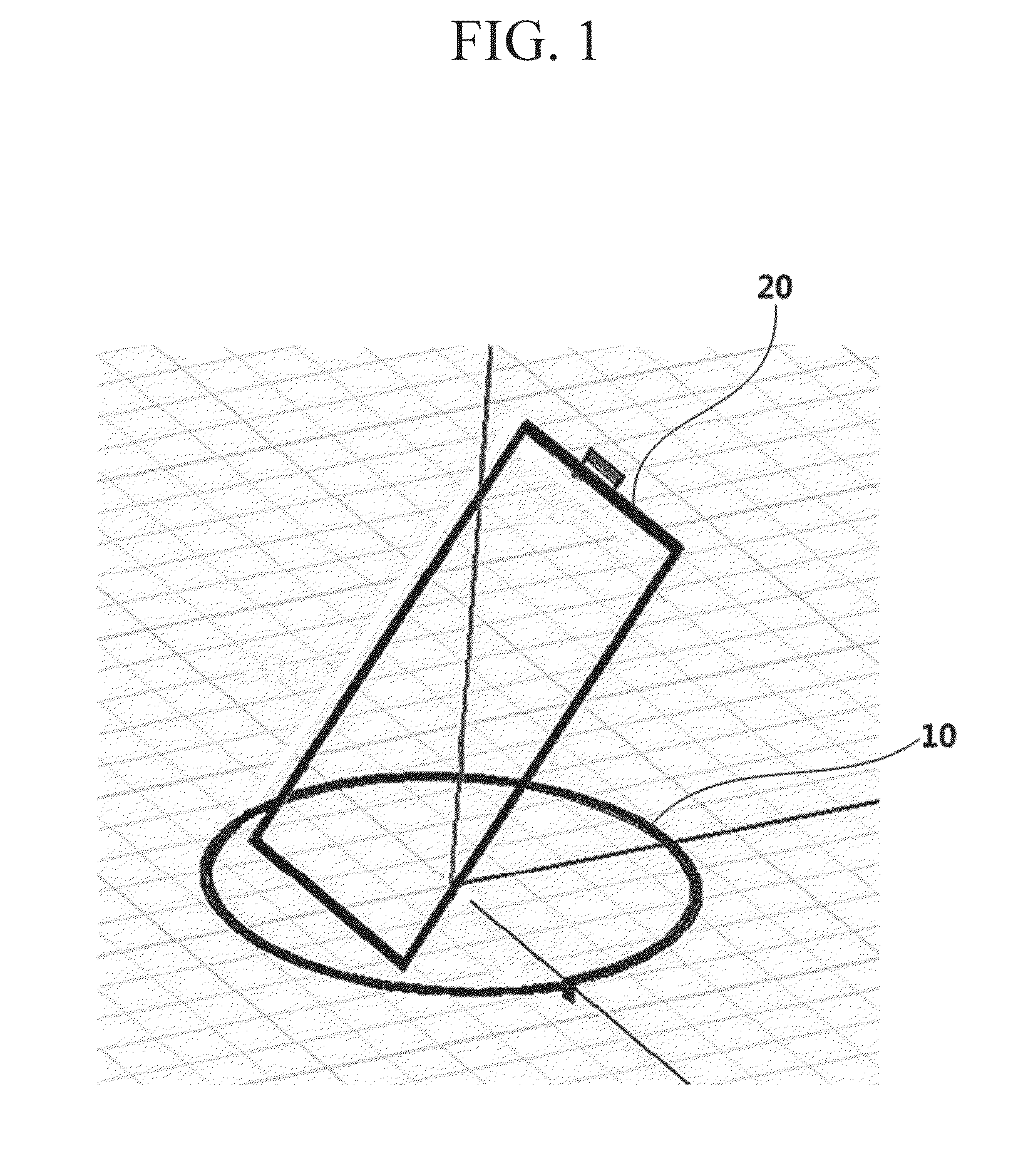
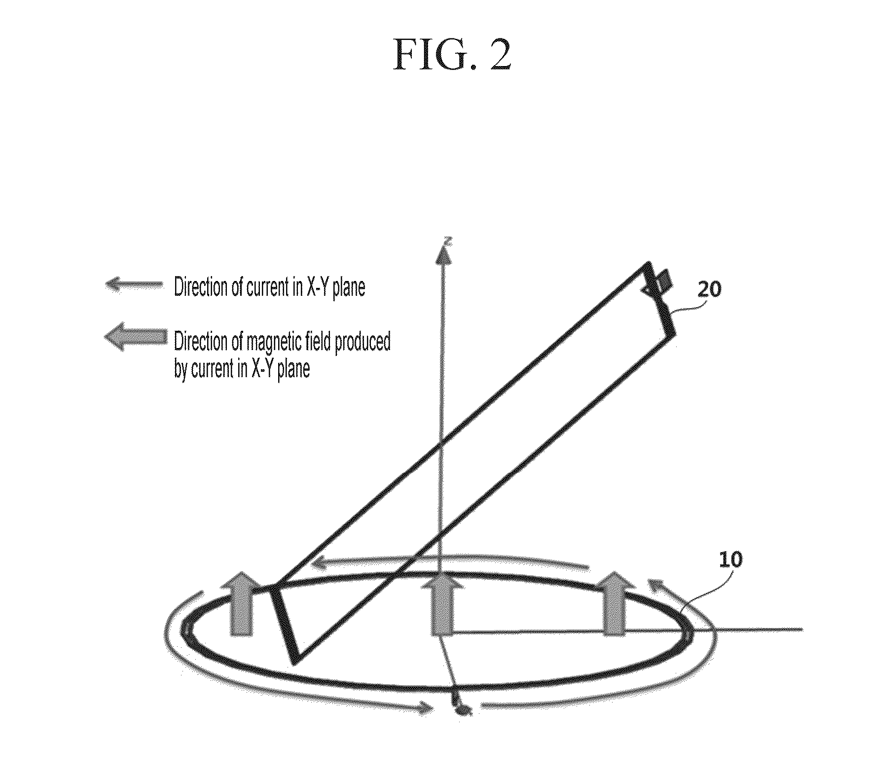
Transmitting antenna and transmitter for wireless power charging
a technology of transmitter and transmitter, which is applied in the direction of inductance, transportation and packaging, polarised antenna unit combination, etc., can solve the problems of electromagnetic induction type charging system, unwieldy, and reduce transmission efficiency quickly, so as to reduce the effect of the position and direction of the receiver, reducing the burden, and facilitating the us
- Summary
- Abstract
- Description
- Claims
- Application Information
AI Technical Summary
Benefits of technology
Problems solved by technology
Method used
Image

Examples
Embodiment Construction
[0035]Technical solutions and advantages of embodiments of the present invention are clearly and completely described in the following with reference to the accompanying drawings. Obviously, the embodiments in the following descriptions are merely part of rather than all of the embodiments of the present invention. All other embodiments obtained by persons of ordinary skill in the art based on the embodiments of the present invention without making creative efforts shall fall within the protection scope of the present invention.
[0036]In order to clarify the present invention, parts that are not related to the description are omitted, and similar elements are given similar reference numerals throughout the specification.
[0037]In the following description, well-known functions or constructions are not described in detail to avoid obscuring the invention in unnecessary detail.
[0038]Throughout this specification and the claims that follow, when it is described that an element is “couple...
PUM
 Abstract
Description
Claims
Application Information