Photon counting imaging method and device with instant retrigger capability

a technology of photon counting and imaging method, applied in the direction of photometry using electric radiation detector, optical radiation measurement, instruments, etc., can solve the problems of increasing power consumption and limited time measurement accuracy

Active Publication Date: 2014-07-10
DECTRIS LTD
View PDF4 Cites 15 Cited by
  • Summary
  • Abstract
  • Description
  • Claims
  • Application Information

AI Technical Summary

Benefits of technology

[0012]The basic problem and the solution according to this inven

Problems solved by technology

Consequently, the achievable time measurement precision is limited by the temporal resolution of the counting clock.
A time counting clock with high frequency would increa

Method used


Image

  • Photon counting imaging method and device with instant retrigger capability
  • Photon counting imaging method and device with instant retrigger capability
  • Photon counting imaging method and device with instant retrigger capability

Examples


Embodiment Construction

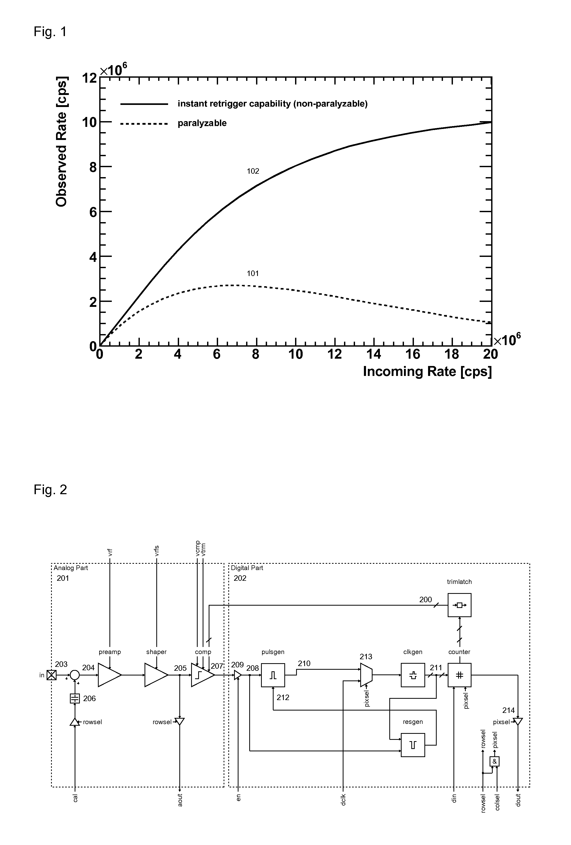
[0023]The generation of an electron-hole pair by the photoeffect is not shown and explained here since this is basic physics and is exhaustively described in U.S. Pat. No. 7,514,688 B2 (WO 2004 / 064168 A1). FIG. 1 shows the observed count rate versus the actual incoming photon rate in a photon counting imaging device. These characteristic curves represent a system-level simulation of statistically distributed pulses with idealized pulse shapes. The lower and dotted curve 101 represents conventional (paralyzable) counting and the upper and solid curve 102 enhanced (non-paralyzable) counting which is obtained by an instant retrigger capability of the counting circuit. This instant retrigger capability is the key characteristic of the present invention.

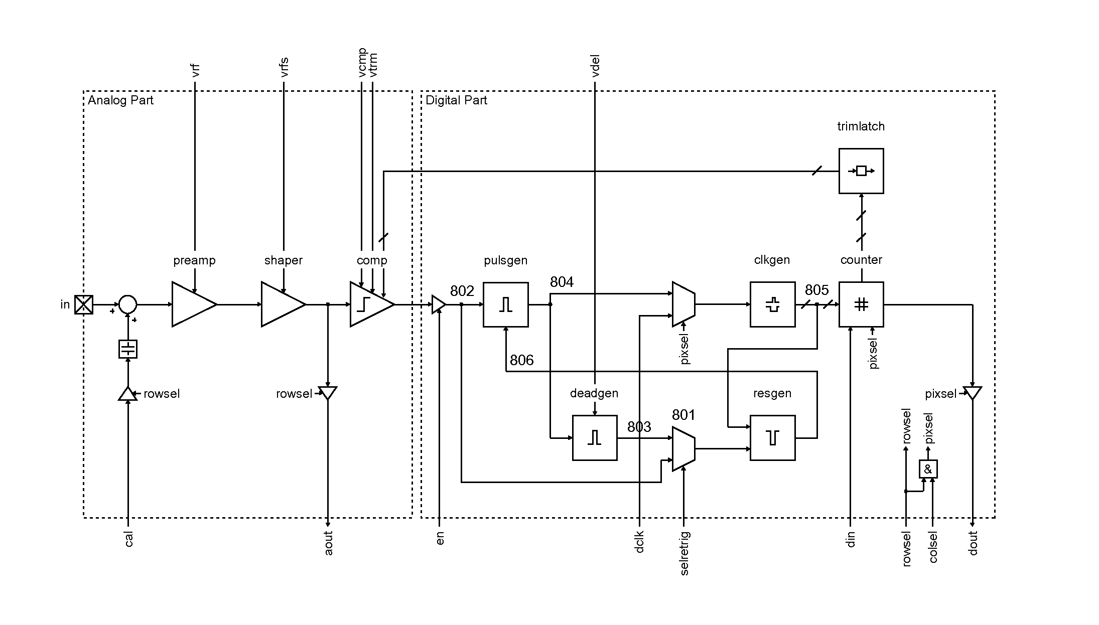
[0024]In FIG. 2, the detailed block diagram of a conventional (paralyzable) readout unit cell (pixel) is shown. This pixel is divided into an analog part 201 and a digital part 202. The analog part 201 includes a bump pad 203 for the inte...


PUM


Abstract

A method for photon counting imaging with improved high-rate counting performance includes the step of applying an instant retrigger capability with adjustable dead time in cells of the detector array and operates an apparatus using a layer of photo-sensitive material, an L×K array of photodetector elements arranged in the layer of the photosensitive material, an N×M array of readout unit cells, including amplifying elements and at least one readout unit cells for at least one photodetector elements. The readout unit cells are controlled by signal processing elements with each readout unit cell having internal signal processing elements to generate a discriminator output signal representing an amplified signal of the electron-hole pairs generated by an incident photon or a number of incident photons in the respective photodetector element. The discriminator output signal is generated by comparing the amplified signal with a predetermined threshold level and the discriminator output signal is generated whenever the amplified signal exceeds the threshold level.

Description

FIELD OF THE INVENTION[0001]This invention relates to an enhanced photon counting imaging method and device for single x-ray counting.[0002]X-ray diffraction patterns are useful in a number of applications, e.g. for the analysis of molecular structures, such as protein and virus molecules, and require photon counting imaging devices. Especially, protein and virus crystallography imposes stringent requirements on x-ray detectors, particularly where the x-ray source is high-flux synchrotron radiation that enables an experiment to be done rapidly.[0003]Furthermore, an important and developing field is time-resolved diffraction experiments using synchrotron radiation, such as crystallography or powder diffraction analysis. Monitoring a time-dependent reaction in a sample, i.e. a crystal or a powder, can elucidate the time-dependent crystal or molecular changes that occur in a chemical reaction as well. High time resolution and speed are often critical in such monitoring.BACKGROUND OF TH...

Claims


Application Information

Patent Timeline
IPC IPC(8): G01T1/17
CPCG01T1/171
Inventor LOELIGER, TEDDYBROENNIMANN, CHRISTIANSCHNYDER, ROGER
Owner DECTRIS LTD
Why Eureka
Try Eureka