Orthodontic Bracket

a bracket and orthodontic technology, applied in the field of orthodontic brackets, can solve the problems of long treatment time, difficult to control the resulting treatment force in all planes of space, and difficult to achieve the effect of reducing the number of patients

Inactive Publication Date: 2014-07-24
PREMIER ORTHODONTIC DESIGNS LLLP
View PDF0 Cites 50 Cited by
  • Summary
  • Abstract
  • Description
  • Claims
  • Application Information

AI Technical Summary

Problems solved by technology

This not only took long periods of time and advanced skills but it was nearly impossible to control the resulting treatment forces applied in all planes of space.
As a result treatment times for patients were often long in duration, and the treatment forces which were applied often had a negative long term impact on the patient's bone and tissue.
However, this design still lacked adequate third order control of tooth axial inclination.
The term “Straightwire Orthodontics” misled many clinicians to believe that only one bracket torque prescription on each anterior tooth was adequate to express a final desired tooth position.
Unfortunately, without bending rectangular arch wires to individualize finishing torque on individual teeth, this had nearly the same effect as treating patients using only round arch wires in the bracket arch wire slot.
Over the years, some clinicians have tried to fill the arch wire slot with larger cross-sectional rectangular arch wires to achieve third order control, but many have found it difficult to finally position teeth due to the binding and friction which is experienced in the arch wire-bracket interface.
The use of these larger dimensioned finishing rectangular arch wires also usually meant the application of unfavorable physical forces both in magnitude, and direction, which made final tooth position far more challenging for the clinician.
This also resulted in a potentially negative, long term impact on the patient's bone and tissue.
It should be readily apparent that the multitude of variations which may impact third order tooth movements are many, and consequently orthodontist typically are not readily able, in a clinical setting, to accurately calculate the amount of third order movement that is needed, and the appropriate amount of force that might be needed or applied to a given tooth to achieve the desired movement.
Further, this miscalculation of the appropriate amount of force to express third order torque may result in excessive discomfort to the patient, and as previously mentioned, potentially negative long term periodontal health issues may arise for the orthodontically treated patient.

Method used


Image

  • Orthodontic Bracket
  • Orthodontic Bracket
  • Orthodontic Bracket

Examples


Embodiment Construction

[0081]This disclosure of the invention is submitted in furtherance of the constitutional purposes of the U.S. Patent Laws “to promote the progress of science and useful arts” (Article 1, Section 8).

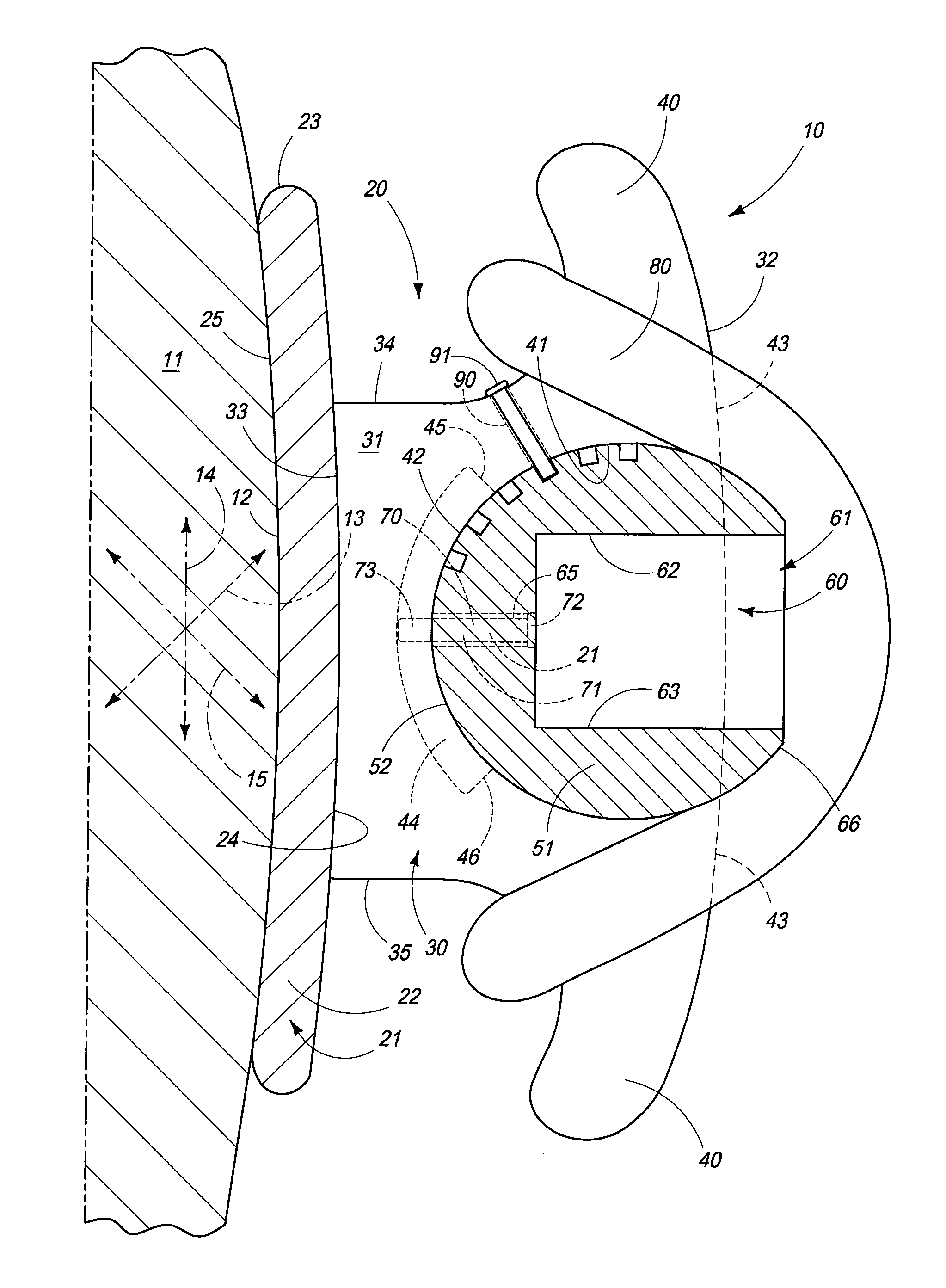
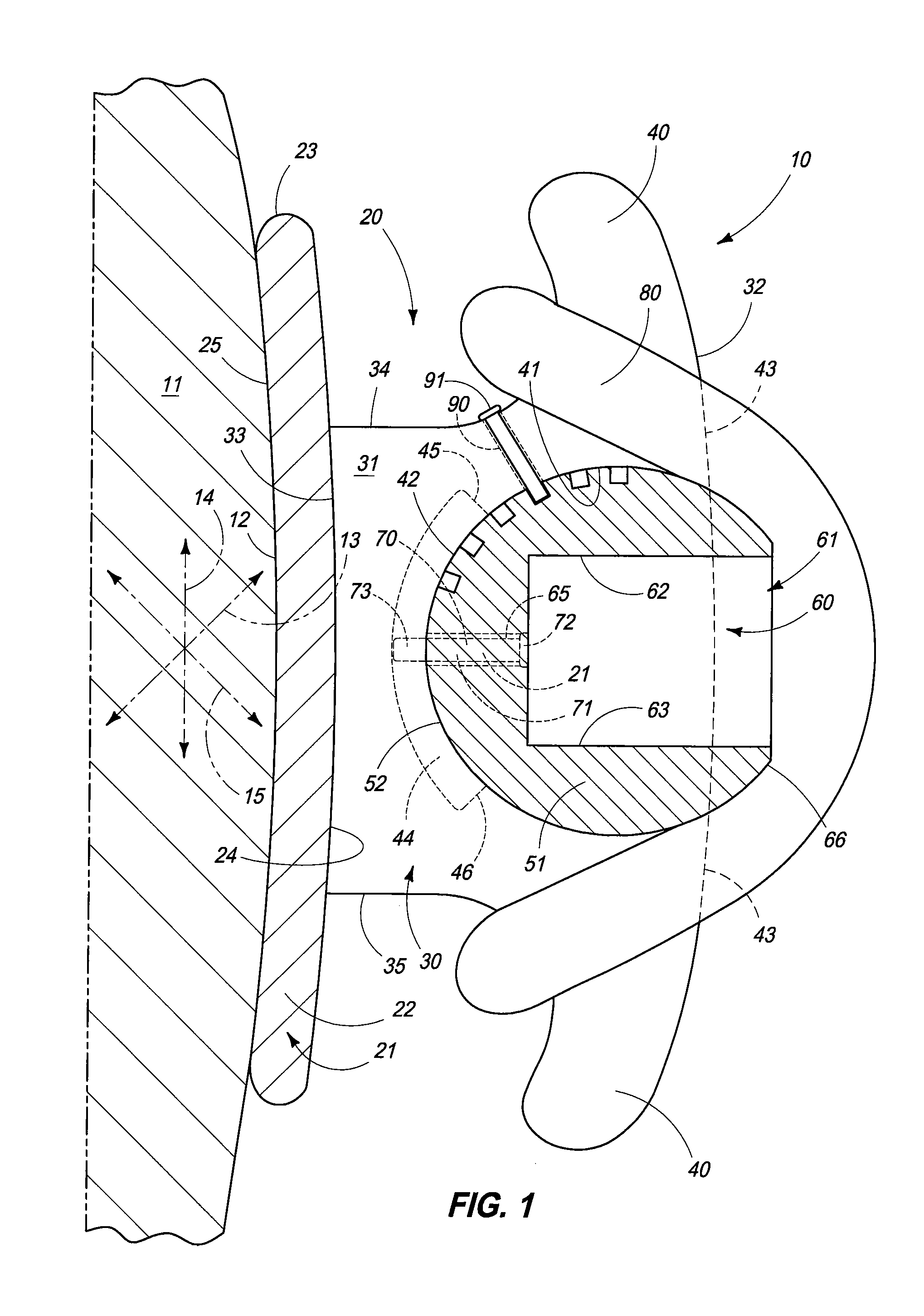
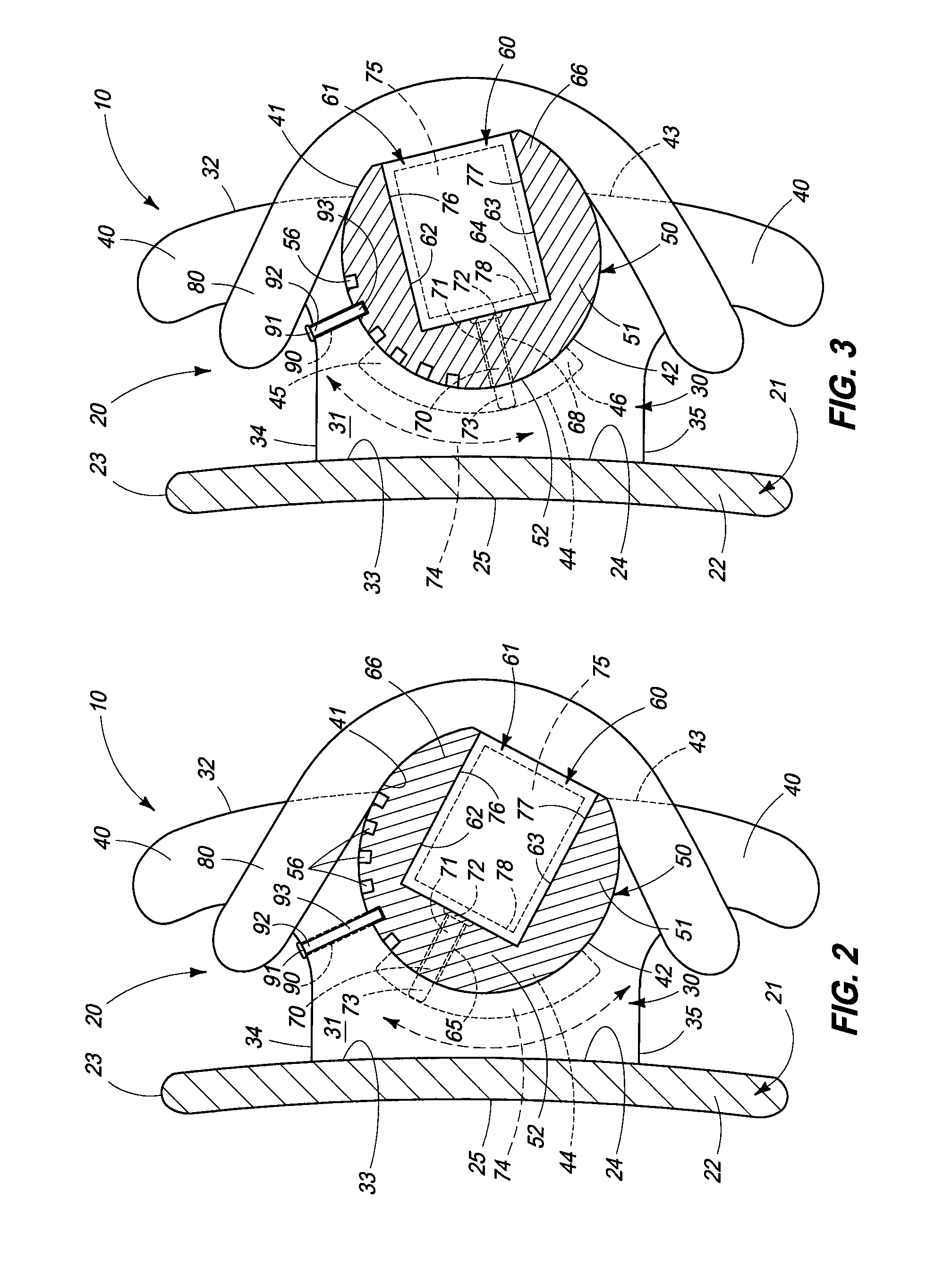
[0082]The present invention is generally indicated by the numeral 10 in FIG. 1 and following. For purposes of the present application, it will be understood that common, repeated numerals, refer to similar structures in the various forms of the invention as disclosed, hereinafter. To appreciate the novelty of the present invention, it should be understood that the orthodontic bracket 10 of the present invention is employed to be releasably affixed on a patient's tooth 11, and in particular, the anterior facing surface 12 thereof. The orthodontic bracket, 10 in combination with the arch wire as will be described, hereinafter, is employed to provide a multiplicity of selective torque expressions which individually, forcibly, act upon the patient's tooth 11. For purposes of this patent appli...


PUM


Abstract

An orthodontic bracket is described and which includes a bracket base which is releasably affixed to a patient's tooth; a bracket body borne on the bracket base and which defines a transversely disposed arch wire slot; and an arch wire received within the arch wire slot, and wherein the orthodontic bracket, acting in combination with the arch wire, is adjustable while affixed to the patient's tooth, to provide a multiplicity of selective torque and / or rotation expressions which individually, forcibly act upon the patient's tooth.

Description

TECHNICAL FIELD[0001]The present invention relates to an orthodontic bracket, and more specifically to an orthodontic bracket which when used in combination with an arch wire, provides a multiplicity of selective torque expressions which individually forcibly act upon a patient's tooth.BACKGROUND OF THE INVENTION[0002]Dr. Edward Angle, the father of modern orthodontics, invented the “Edgewise Appliance” and introduced it to the specialty in 1925. His design was a significant advancement in the treatment of patients by placing a mesio-distal horizontal rectangular slot in the bracket labial, and buccal surfaces thereby allowing clinicians to better position teeth. By bending round and / or rectangular arch wires and then placing them into these horizontal rectangular bracket slots, improved control of tooth position was achieved in three planes of space. Modern orthodontics has categorized these patient tooth movements into the three previously mentioned planes of space as first, secon...

Claims


Application Information

Patent Timeline
Patent Type & Authority Applications(United States)
IPC IPC(8): A61C7/22A61C7/30
CPCA61C7/22A61C7/303A61C7/14
Inventor DAMON, PAUL L.DAMON, DWIGHT H.
Owner PREMIER ORTHODONTIC DESIGNS LLLP
Why Eureka
Try Eureka