Workpiece separating device

Inactive Publication Date: 2014-08-28
SHENZHEN FUTAIHONG PRECISION IND CO LTD +1
View PDF11 Cites 3 Cited by
  • Summary
  • Abstract
  • Description
  • Claims
  • Application Information

AI Technical Summary

Problems solved by technology

However, it is difficult to separate the foam with small sizes, 4.8 mm×4.

Method used


Image

  • Workpiece separating device
  • Workpiece separating device
  • Workpiece separating device

Examples


Example

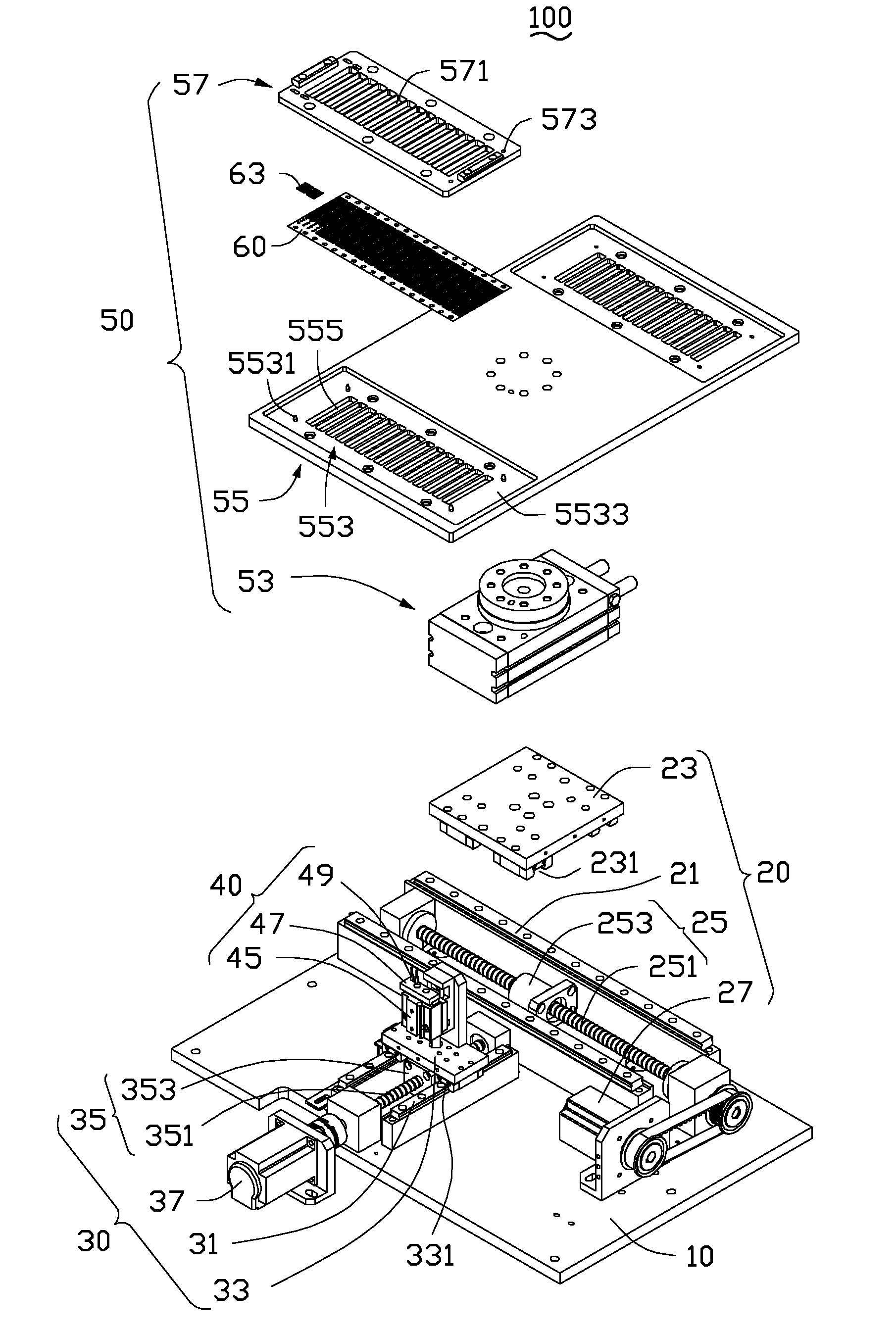
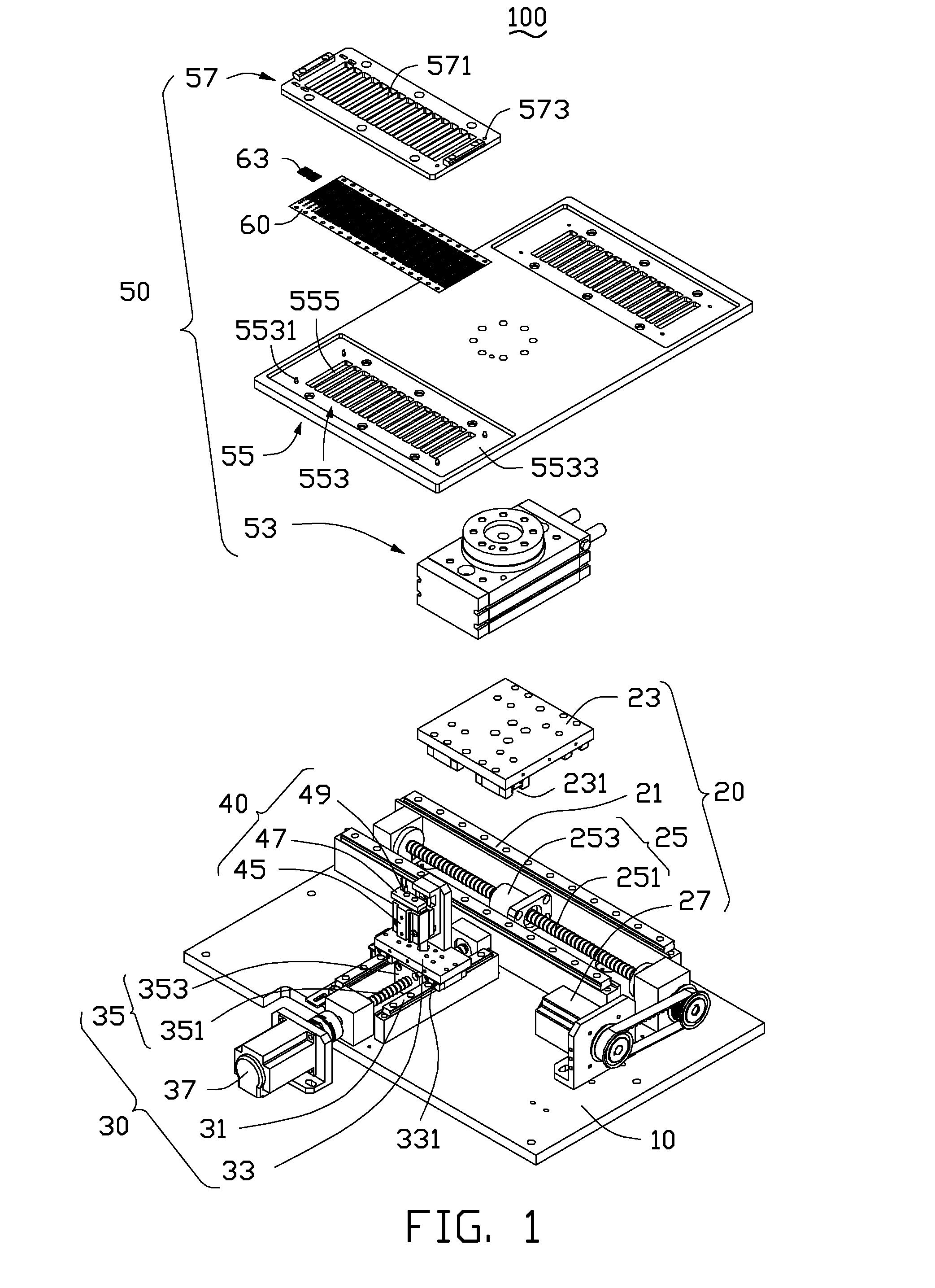
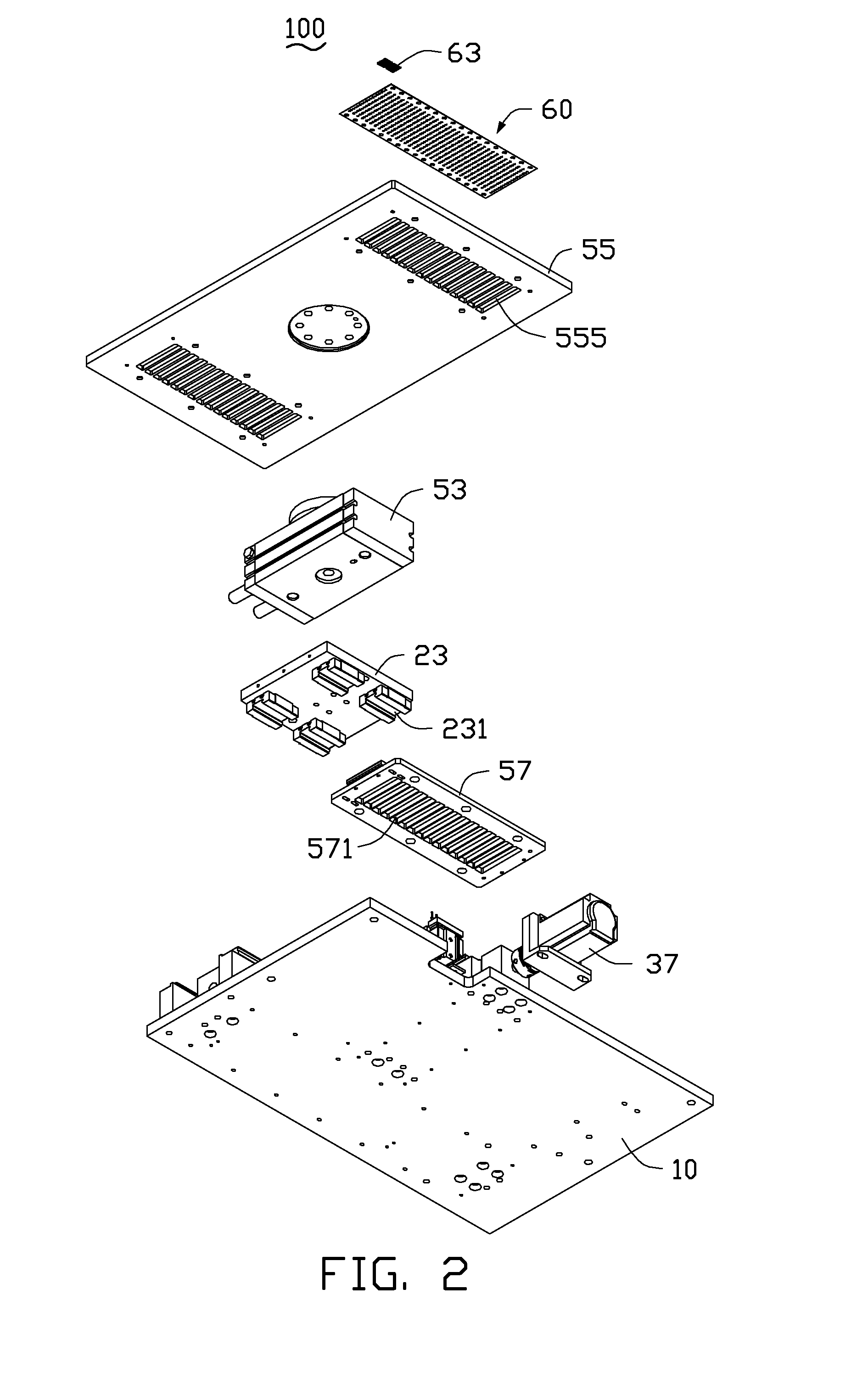
[0011]FIGS. 1-3 show an exemplary embodiment of a workpiece separating device 100. The workpiece separating device 100 may be used for separating workpieces 63 from support sheets 60 where the workpieces 63 are adhered. Each of the support sheets 60 defines two through holes 612 (best shown in FIG. 4) corresponding to each workpiece 63. The workpieces 63 can be foam pieces or other elements of electronic devices. The workpiece separating device 100 includes an assembling board 10, a first driving unit 20, a second driving unit 30, a lifting unit 40, and a positioning assembly 50. The first and second driving units 20, 30 are assembled on the assembling board 10. The lifting unit 40 is slidably assembled to the second driving unit 30. The positioning assembly 50 is slidably assembled to the first driving unit 20. The support sheet 60 is positioned on the positioning assembly 50.

[0012]The first driving unit 20 includes two first sliding rails 21, a first sliding block 23, a first ball...


PUM


Abstract

A workpiece separating device for separating workpieces from support sheets includes a lifting unit and a positioning assembly supporting the support sheets with the workpieces adhered. The lifting unit includes a lifting cylinder and two pins raised and lowered by the lifting cylinder. The two pins are raised by the lifting cylinder to push the workpieces, thereby separating the workpieces from the support sheets in turn. A method for separating workpieces from support sheets using the present device is also provided.

Description

BACKGROUND[0001]1. Technical Field[0002]The present disclosure generally relates to devices for separating workpieces (e.g., foam) from support materials.[0003]2. Description of Related Art[0004]Foam is widely used in the manufacturing of electronic devices. Before being assembled, foam is adhered on support materials, such as paper boards. During assembly, the foam having a relatively large size, can be effectively separated from the support materials using vacuum grip devices. However, it is difficult to separate the foam with small sizes, 4.8 mm×4.8 mm for example, from support materials using vacuum grip devices alone.[0005]Therefore, there is room for improvement within the art.BRIEF DESCRIPTION OF THE DRAWINGS[0006]Many aspects of the disclosure can be better understood with reference to the drawings. The components in the drawings are not necessarily drawn to scale, the emphasis instead being placed upon clearly illustrating the principles of the disclosure. Moreover, in the ...

Claims


Application Information

Patent Timeline
IPC IPC(8): B23P19/04
CPCB23P19/04G06F1/16Y10T29/49822Y10T29/49824Y10T29/53274Y10T29/53283Y10T29/53683
Inventor GAO, JIEYU, BINGJIN, JIAN-PING
Owner SHENZHEN FUTAIHONG PRECISION IND CO LTD
Why Eureka
Try Eureka