Supercharge Your Innovation With Domain-Expert AI Agents!

Support plate for bearings

a technology for supporting plates and bearings, which is applied in the direction of rigid support of bearing units, manufacturing tools, mechanical equipment, etc., can solve the problems of high local deformation, excessive loading of the material of the supporting plate, and formation of fractures

Active Publication Date: 2014-09-04
SEG AUTOMOTIVE GERMANY GMBH
View PDF3 Cites 0 Cited by
  • Summary
  • Abstract
  • Description
  • Claims
  • Application Information

AI Technical Summary

Benefits of technology

This design effectively reduces the transmission of high mechanical loadings to generator components by absorbing oscillations through material deformation and fracture, changing the generator's response characteristic and reducing maximum load through damping effects, independent of fracture face friction.

Problems solved by technology

To this end, notches can be made at defined points of the support plate, which notches lead to high but locally delimited excessive loadings of the material of the support plate.
If said delimited excessive loadings exceed a limiting value, this necessarily leads to the occurrence of a plastic deformation and, as a final consequence, to the formation of fractures.

Method used


Image

  • Support plate for bearings
  • Support plate for bearings
  • Support plate for bearings

Examples


Embodiment Construction

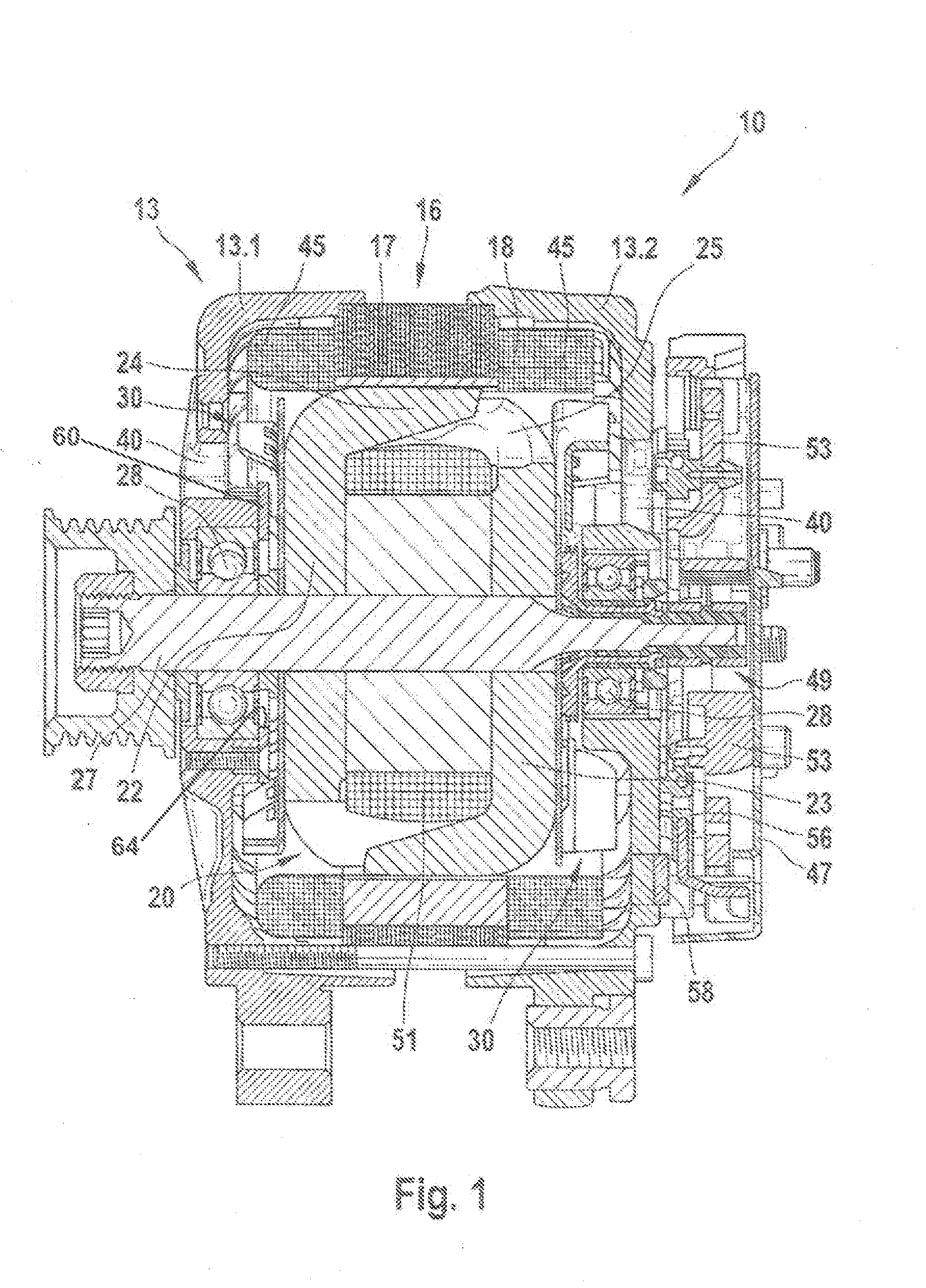
[0030]The illustration according to FIG. 1 shows a section through an electric machine 10, configured here as a generator or three-phase generator for motor vehicles. Said electric machine 10 has, inter alia, a two-part housing 13 which consists of a first bearing plate 13.1 and a second bearing plate 13.2. The first bearing plate 13.1 and the second bearing plate 13.2 receive a stator 16 between them, which stator 16 firstly consists of a substantially circularly annular stator iron 17 and in the radially inwardly directed, axially extending grooves of which a stator winding 18 is inserted. Said annular stator 16 surrounds a rotor 20 with its radially inwardly directed grooved surface, which rotor 20 can be configured as a claw pole rotor. The rotor 20 consists, inter alia, of two claw pole plates 22 and 23, on the external circumference of which claw pole fingers 24 and 25 which extend in the axial direction are arranged. The claw pole plates 22 and 23 are arranged within the roto...


PUM

PropertyMeasurementUnit
frequencyaaaaaaaaaa
frequencyaaaaaaaaaa
accelerationsaaaaaaaaaa

Abstract

A support device and method for fixing a bearing on a bearing shield of a housing of an electric machine. Rotatably mounted in the support device is a rotor with a shaft. The support device is substantially flat and comprises a plurality of fastening openings that are grouped about a central opening. The support device comprises at least one design break point that acts to provide a local limit to the excess stress in the material of the support device.

Description

CROSS-REFERENCE TO RELATED APPLICATIONS[0001]This application is a continuation of U.S. patent application Ser. No. 13 / 121,705, filed May 10, 2011, which is a U.S. national phase filing of PCT / EP2009 / 062516, filed Sep. 28, 2009, which claims priority to German Patent Application 10 2008 042 552.4, filed Oct. 2, 2008.BACKGROUND OF THE INVENTION[0002]As a rule, air-cooled generators for applications in the automotive sector are mounted by means of a locating bearing in a first bearing plate (A bearing plate) and a floating bearing in a second bearing plate (B bearing plate). A ball bearing which is used as a bearing is fixed axially here between a bearing plate and a support plate. As a result of the generally present bearing play, oscillations of the rotor occur as overall body in the axial direction. This phenomenon which is also called rotor bouncing occurs as a rule between 100 Hz and 500 Hz and is generally associated with very high mechanical loadings in the generator on various...

Claims


Application Information

Patent Timeline
Patent Type & Authority Applications(United States)
IPC IPC(8): F16C35/00
CPCF16C35/00F16C35/067H02K5/1732F16C19/06F16C19/522F16C19/54F16C2380/26F16C2226/60Y10T29/49947F16C33/76
Inventor EINBOCK, STEFANRIOU, VINCENTSCHROTH, RUEDIGER
Owner SEG AUTOMOTIVE GERMANY GMBH
Features
  • R&D
  • Intellectual Property
  • Life Sciences
  • Materials
  • Tech Scout
  • Unparalleled Data Quality
  • Higher Quality Content
  • 60% Fewer Hallucinations
Learn More