
Converter circuit

Active Publication Date: 2008-08-21
INFINEON TECH AMERICAS
View PDF6 Cites 34 Cited by
  • Summary
  • Abstract
  • Description
  • Claims
  • Application Information

AI Technical Summary

Benefits of technology

[0012]A first aspect of the invention addresses the phase turn on perturbation that can occur if the low side switch is turned on first, which means that the phase being turned on will sink current and put more load on the already running phases. This results in a large perturbation in the current sharing loop and can also lead to saturation of the inductor for the already running phases. To solve this problem, the invention assures that the high side switch is always turned on ahead of the low side switch, thereby minimizing the impact on dynamic current sharing among the phases and improving the transient response of the converter.
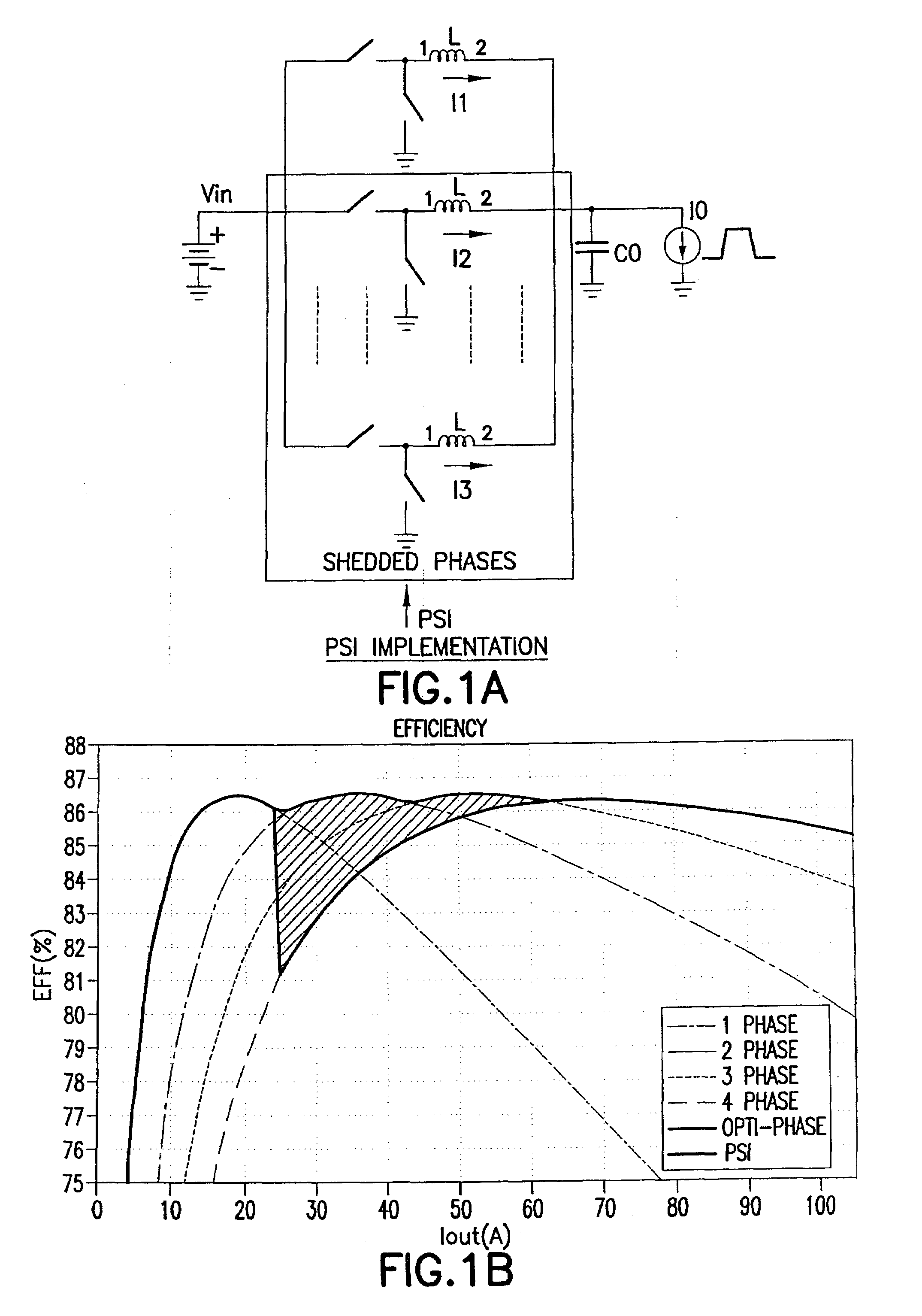
[0013]According to yet a further aspect, the invention utilizes the power state indication (PSI) output from the CPU such that phases are shed with a preset delay after the PSI signal requiring phase(s) to be shed is received. Such an arrangement allows higher bandwidth to respond to load change and less output voltage variation.

Problems solved by technology

This results in a large perturbation in the current sharing loop and can also lead to saturation of the inductor for the already running phases.

Method used


Image

  • Converter circuit
  • Converter circuit
  • Converter circuit

Examples


Embodiment Construction

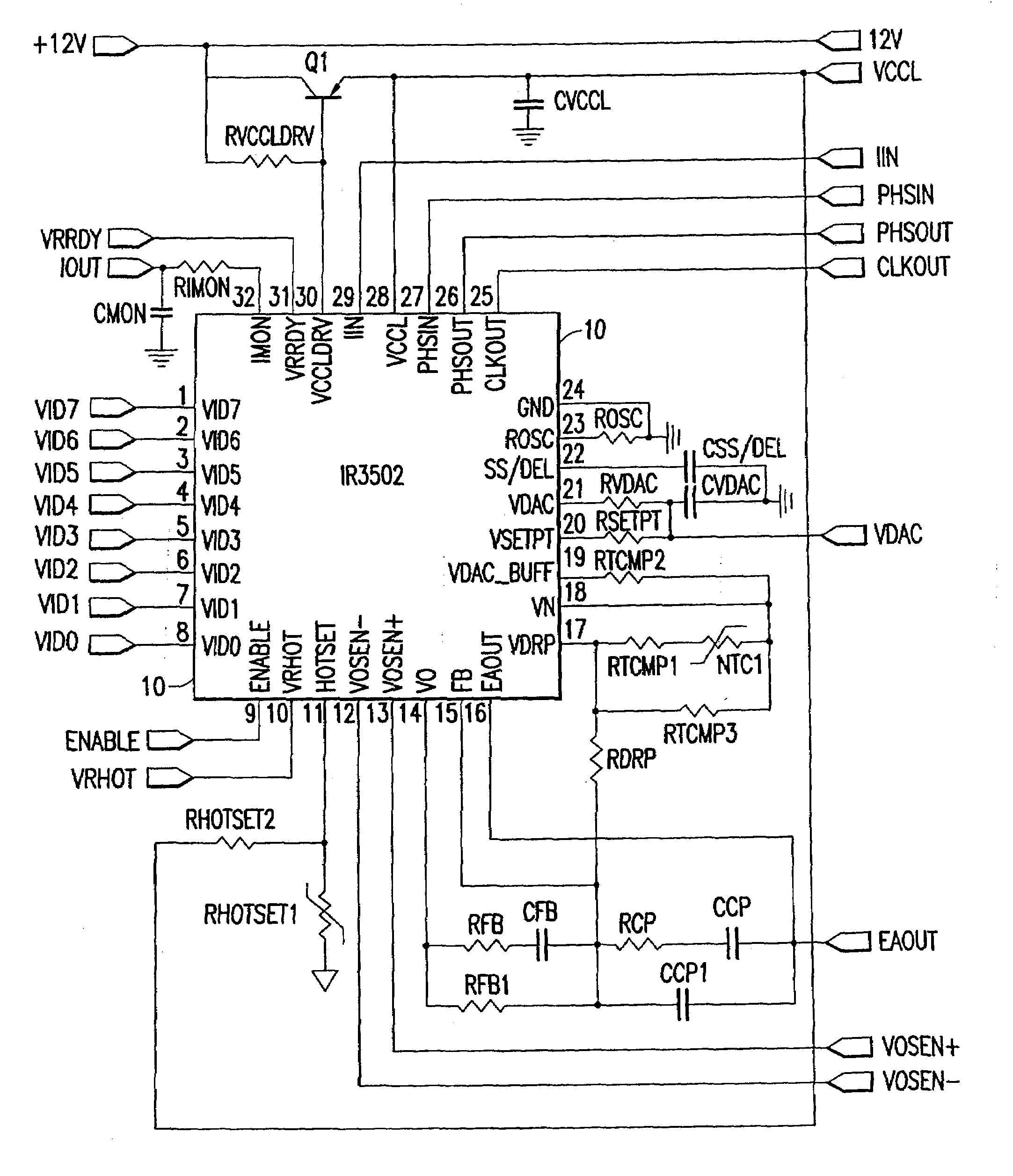
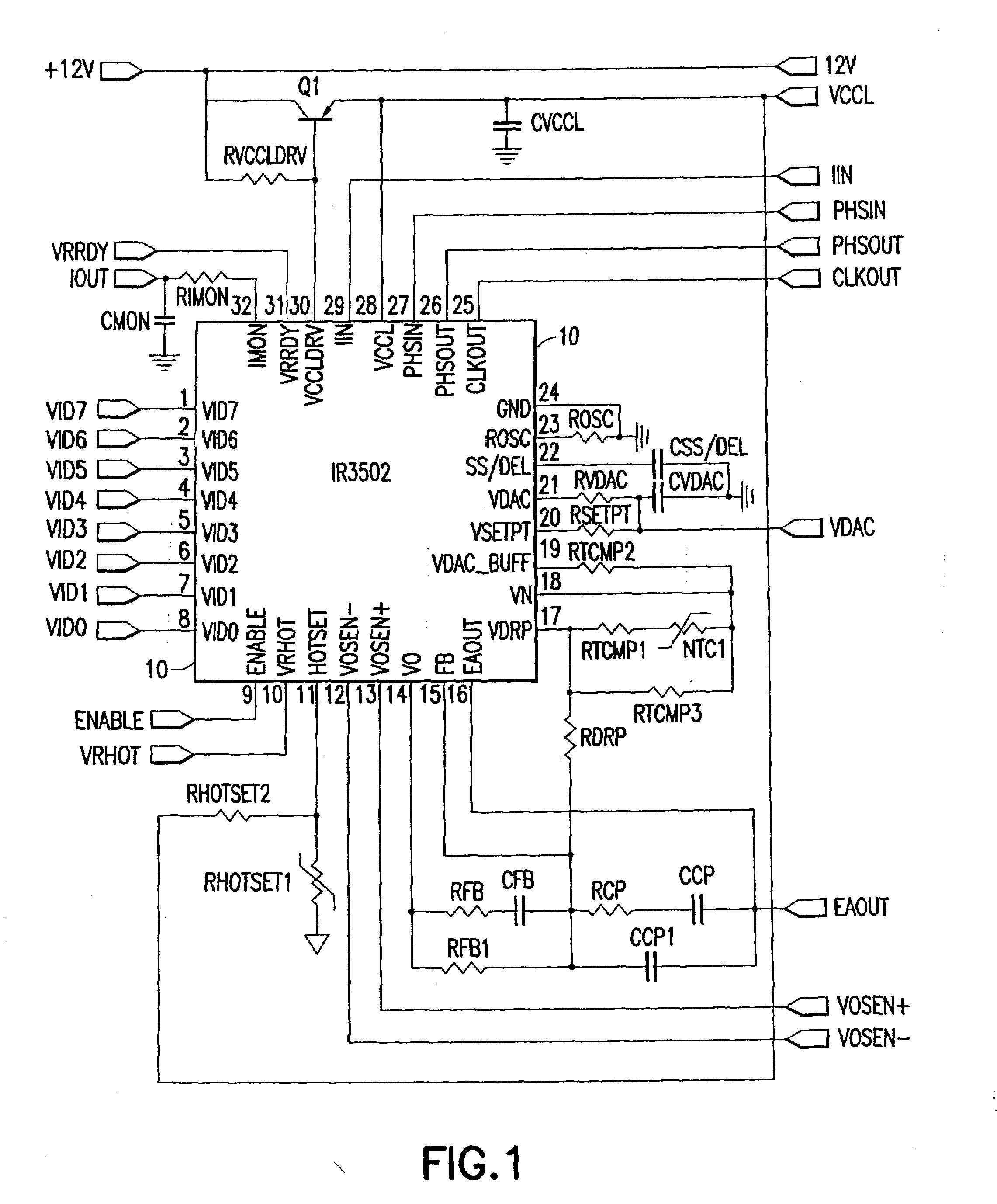
[0031]With reference to FIGS. 1 and 2, these figures show a two-phase multiphase converter. FIG. 1 shows the control circuit including a control IC 10 and FIG. 2 shows the output converter circuits including phase ICs 100. Since there are two phase ICs 100, a two-phase multiphase converter is shown. Additional phases can be provided by implementing additional phase ICs 100 and connecting the outputs together and the various inputs together either in parallel as shown for certain connections, or in daisy chain arrangement for the phasing signals from the control IC as well known to those of skill in the art, and particularly as known in connection with the International Rectifier X-Phase line of multiphase converter integrated circuits.

[0032]Turning to FIG. 1, this shows the control integrated circuit 100. The control integrated circuit illustratively receives a 12 volt supply and produces a low side driver supply VCCL and ground GND. In addition, the control IC receives VID inputs, ...


PUM


Abstract

A multiphase converter comprising a plurality of converter circuits, each converter circuit having series connected high and low side switches connected across a voltage bus with a common node provided therebetween, each of the common nodes connected through a respective inductor to an output node of the converter coupled to a load, the high and low side switches each being controlled by a control circuit to provide a desired output voltage at the output node, the control circuit including a first circuit for disabling and enabling at least one phase in response to a condition of the load, the circuit causing the high side switch to be turned on prior to the lower side switch when a disabled phase is enabled.

Description

CROSS-REFERENCE TO RELATED APPLICATIONS[0001]The present application claims the benefit and priority of U.S. Provisional Application Ser. No. 60 / 890,061 filed Feb. 15, 2007 entitled ONE NTC THERMAL COMPENSATION AND POWER STATE INDICATOR IMPLEMENTATION FOR DC-DC CONVERTER, the entire disclosure of which is hereby incorporated by reference.BACKGROUND OF THE INVENTION[0002]The present invention relates to DC-DC converters and in particular, to a DC-DC converter having improved features including improved transient response in a multiphase converter application, improved response to a power state indication signal indicating the load condition, thermal compensation for the inherent DC resistance of the phase output inductors and providing improved converter output current information.[0003]In a running multiphase buck converter, when a phase that was previously shut down is turned on, if the low side switch is turned on before the high side switch, this can result in a perturbation in t...

Claims


Application Information

Patent Timeline
IPC IPC(8): G05F1/40G05F1/10
CPCH02M3/1584
Inventor CROWTHER, MARKWU, WENKAISCHUELLEIN, GEORGE
Owner INFINEON TECH AMERICAS
Learn More