Trim cap illuminated channel letter lighting system and letter construction system

a technology of lighting system and letter construction system, which is applied in the direction of lighting and heating equipment, instruments, display means, etc., can solve the problems of relatively short lifespan of light sources, relatively low electrical efficiency, and relatively short lifespan of incandescent bulbs, neon bulbs and fluorescent tubes

Active Publication Date: 2014-09-18
THE SLOAN COMPANY INC DBA SLOANLED
View PDF4 Cites 2 Cited by
  • Summary
  • Abstract
  • Description
  • Claims
  • Application Information

AI Technical Summary

Problems solved by technology

One of the problems associated with the conventional lighting units and systems is that their light sources can experience relatively short lifespans and they can have relatively low electrical efficiency.
Incandescent bulbs, neon bulbs and fluorescent tubes have a relatively short lifespan, particularly when compared to other light sources, such as typical LEDs.
These light sources are also electrically inefficient and providing sufficient lighting, especially in large lighting applications, requires the consumption of significant energy.
Neon bulbs can also experience difficulty with cold starting, which can lead to failure of the neon bulb.
Incandescent lights are very energy-inefficient light sources with a vast majority of the electricity they consume being released as heat rather than light.
Fluorescent light bulbs are more energy efficient than incandescent light bulbs, but are still relatively inefficient.
Neon light tubes need to be bent or formed into the shape corresponding to the housing, which can be labor intensive, especially for channel letter housings.
As such, neon tubes are fragile and are more susceptible to breakage during transit and installation.
Neon light tubes are powered by 4,000-15,000 Volts AC and present a significantly higher electrical hazard potential.
In addition, LEDs can have a significantly longer operational lifetime.
Incandescent light bulbs have relatively short lifetimes, with some having a lifetime in the range of about 750-1,000 hours.
Fluorescent bulbs can also have lifetimes longer than incandescent bulbs such as in the range of approximately 10,000-20,000 hours, but provide less desirable color reproduction.
However, mounting the LED light units on the rear wall could result in the channel letter exhibiting bright and / or dark spots on the face because of reduced overlap of emitted light from the LED light units.

Method used


Image

  • Trim cap illuminated channel letter lighting system and letter construction system
  • Trim cap illuminated channel letter lighting system and letter construction system
  • Trim cap illuminated channel letter lighting system and letter construction system

Examples


Embodiment Construction

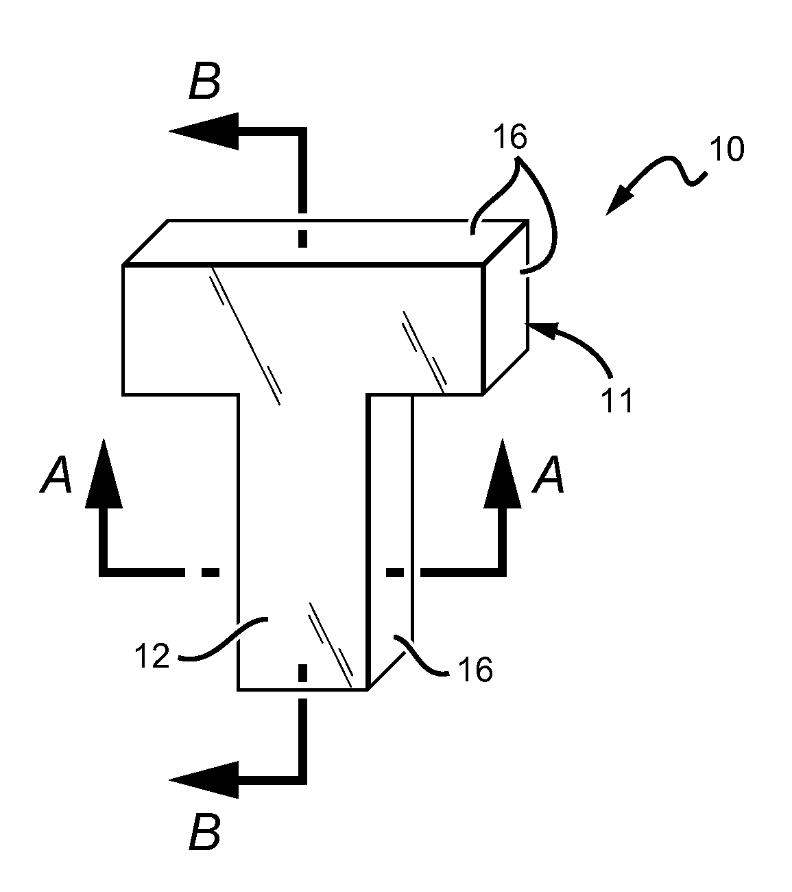
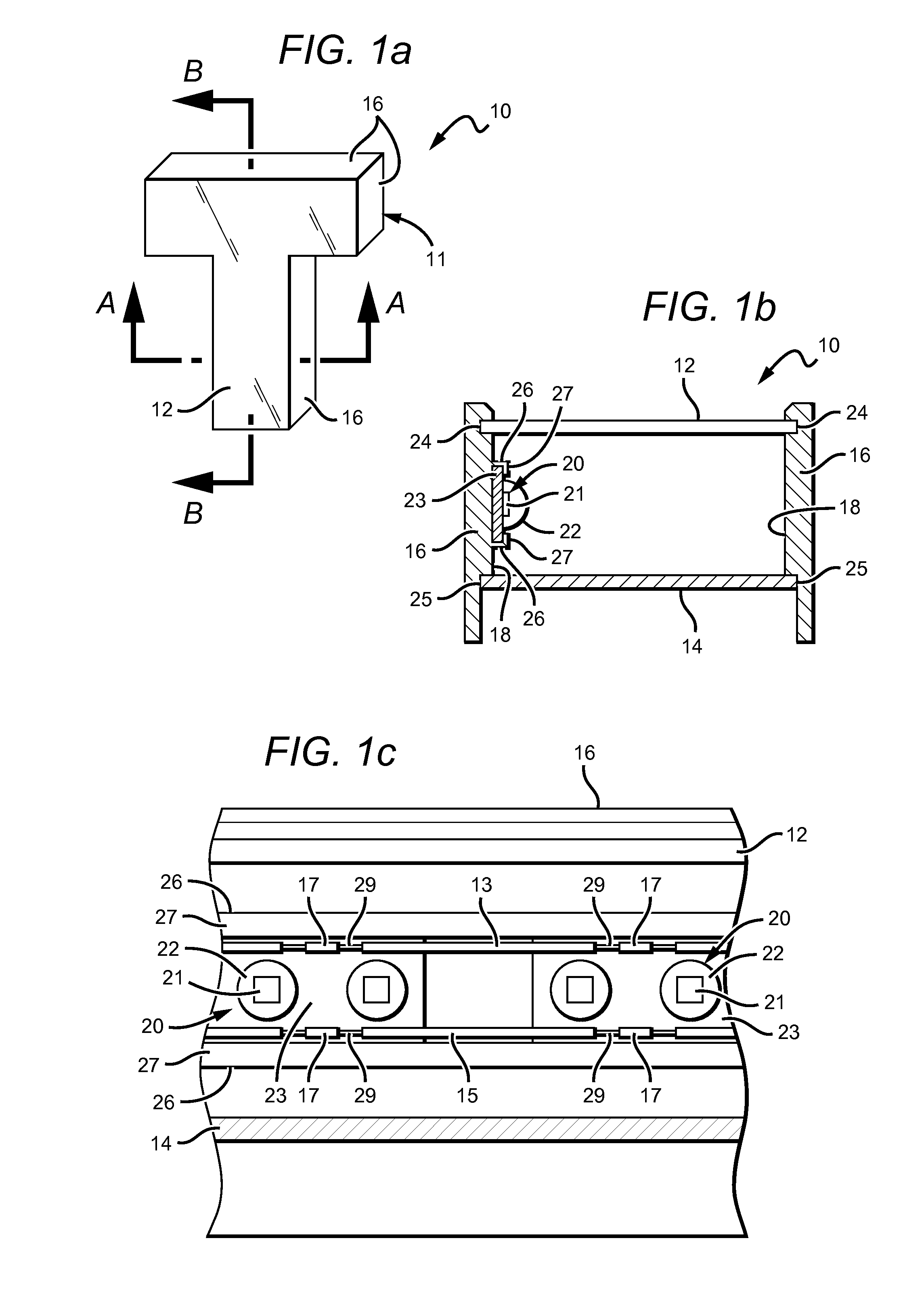
[0022]Embodiments of the invention provide a channel letter lighting system that utilizes light emitting units having a controlled emission and generally arranged to provide uniform illumination to a channel letter.

[0023]The systems according to the present invention provide lighting units that are interconnected in a chain by electrical conductors so that an electrical signal applied to the input end of the conductors spreads to the lighting units, causing them to emit light. The lighting unit can comprise many different materials and can be used in many different lighting applications, such as but not limited to channel letter lighting. The lighting unit according to the present invention can be arranged in many different ways with many different components, and is generally arranged to provide uniform illumination to a channel letter.

[0024]The invention is described herein with reference to certain embodiments, but it is understood that the invention can be embodied in many diffe...


PUM


Abstract

A channel letter lighting system comprising a channel letter housing including a light transmissive face, a rear wall and at least one trim cap adapted to receive the light transmissive face and rear wall. A plurality of light emitting units within the channel letter housing and at least one optical element proximate the plurality of light emitting units, wherein the at least one optical element is configured to direct light emitted from the plurality of light emitting units in a direction away from the face and towards the rear wall or the opposing trim cap. The channel letter lighting system arranged to provide low profile channel letters.

Description

BACKGROUND OF THE INVENTION[0001]1. Field of the Invention[0002]This invention generally relates to channel letter lighting systems, and more particularly to LED based low profile channel letter lighting systems.[0003]2. Description of the Related Art[0004]Display units, such as light boxes, cabinet signs and channel letters are commonly found on the outside of buildings or businesses and are often used to advertise the name of the business or products. Typical light boxes and cabinet signs are constructed of aluminum or plastic housing having the shape of a box and are approximately 5″ deep. The housing sometimes has a swing open frame to allow for easily changing the advertising graphics within. The top opening in the housing, or surface, is covered by a translucent or clear lens that transmits light from within the housing. The advertisement graphic is placed under this lens so that it is between the lens and the lighting units inside the light box. This allows the graphic to be ...

Claims


Application Information

Patent Timeline
Patent Type & Authority Applications(United States)
IPC IPC(8): G09F13/04
CPCG09F13/0404
Inventor QUAAL, BRUCEFERRIE, TIMOTHY DREWLIND, JUSTINCHU, CHADMEYER, AARON
Owner THE SLOAN COMPANY INC DBA SLOANLED
Why Eureka
Try Eureka