Linear ultrasonic motor and lens apparatus and image pickup apparatus using the same

a technology of ultrasonic motors and lens devices, applied in piezoelectric/electrostrictive/magnetostrictive devices, mountings, instruments, etc., can solve the problem of decreasing the property of equal transmission members, and achieve the effect of efficient supply of driving for

Active Publication Date: 2014-10-02
CANON KK
View PDF5 Cites 50 Cited by
  • Summary
  • Abstract
  • Description
  • Claims
  • Application Information

AI Technical Summary

Benefits of technology

[0010]The present invention can provide a linear ultrasonic motor which can efficiently provide a driving force to a body to be driven.

Problems solved by technology

However, there has been a problem that when the pressurization force is excessively large, an equalizing property for a transmission member decreases.

Method used


Image

  • Linear ultrasonic motor and lens apparatus and image pickup apparatus using the same
  • Linear ultrasonic motor and lens apparatus and image pickup apparatus using the same
  • Linear ultrasonic motor and lens apparatus and image pickup apparatus using the same

Examples


exemplary embodiment 1

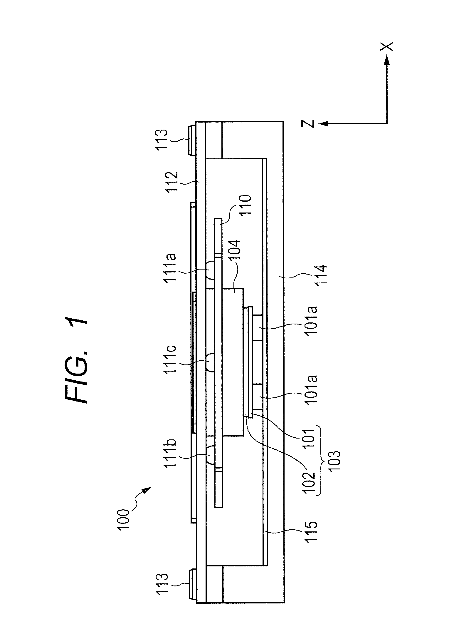
[0026]FIG. 1 is a side view of a linear ultrasonic motor 100 when viewed from the Y-axis direction, which is a first exemplary embodiment of the present invention, and the movable part is in a middle position.

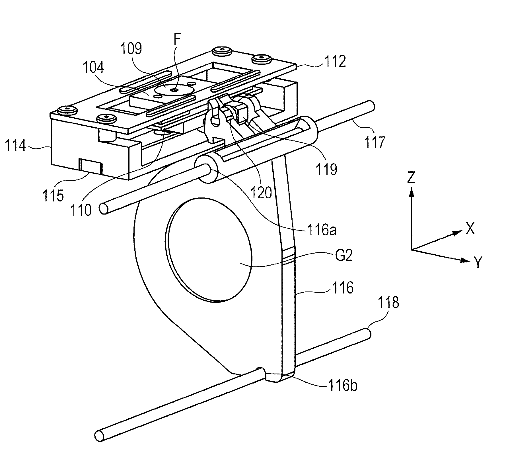
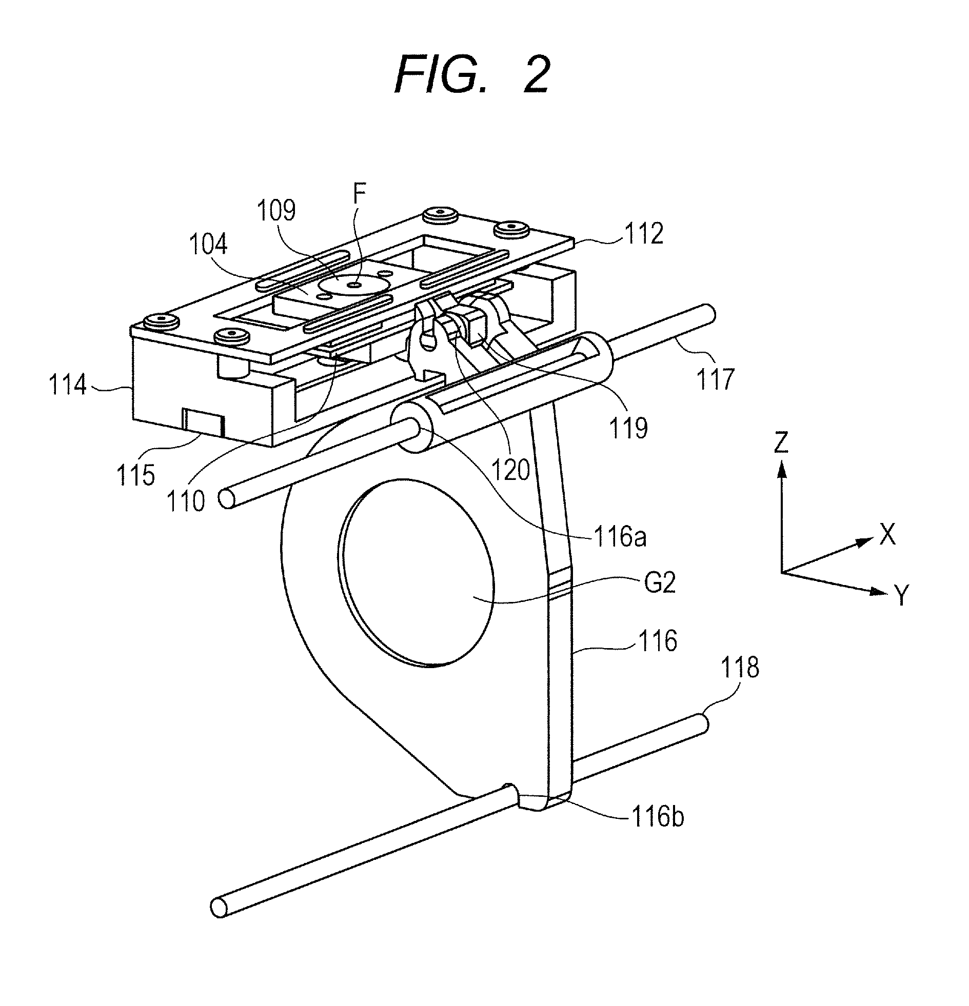
[0027]FIG. 2 is a perspective view of the linear ultrasonic motor 100 to which a lens retention frame has been connected, and the movable part is in a middle position.

[0028]FIG. 3 is an exploded perspective view of the linear ultrasonic motor 100 to which the lens retention frame is connected.

[0029]Firstly, the structure of the linear ultrasonic motor 100 will be described below with reference to FIG. 1, FIG. 2 and FIG. 3.

[0030]The linear ultrasonic motor 100 in the present exemplary embodiment has a longitudinal axis in an X-axis direction, and is formed of each member which will be described below. A vibration plate 101 has a piezoelectric element 102 fixed thereon by a well-known adhesive or the like, and the piezoelectric element 102 excites a vibrator 103 by voltage applie...

exemplary embodiment 2

[0052]FIG. 6 is a sectional view of an essential part of a linear ultrasonic motor which is a second exemplary embodiment of the present invention. The reference numerals of members having functions which overlap with those in the first exemplary embodiment shall be common in the present figure. In addition, the descriptions concerning contents of which the structures and functions are common with those in the first exemplary embodiment will be omitted.

[0053]In the first exemplary embodiment, the transmission part provided on the vibrator support member 104 and the pivot member 119 are structured so as to be engaged with each other. On the other hand, the present exemplary embodiment is structured so that the transmission part 107a of the spring retention member 107, which penetrates through the spring keep plate and extends to the outside, is provided in the spring retention member 107, and the pivot member 119 is engaged with the transmission part 107a of the spring retention memb...

exemplary embodiment 3

[0058]FIG. 7 is a sectional view of an essential part of a linear ultrasonic motor which is a third exemplary embodiment of the present invention. The reference numerals of members having functions which overlap with those in the first exemplary embodiment shall be common in the present figure. In addition, the descriptions concerning contents of which the structures and functions are common with those in the first exemplary embodiment will be omitted.

[0059]In the first exemplary embodiment, the vibrator support member 104 and the pivot member 119 have been structured so as to be engaged with each other on the side face portion of the vibrator support member 104. In contrast, in the structure of the linear ultrasonic motor 300 according to the embodiment, only the arrangement of the transmission part 104a is different that is formed integrally with the vibrator support member 104 of the linear ultrasonic motor 100 and has a spherical surface shape, which has been described in the fi...


PUM


Abstract

A linear ultrasonic motor includes a vibrator having a piezoelectric element, a movable part applying a pressurization force to the vibrator and bringing the vibrator into pressurized contact with a base part, a cover part being fixed to the base part, a rolling part being rollably held between a movable guide part of the movable part and a cover guide part of the cover part, and a body to be driven having a transmission member that is pivotably supported and being able to move only in the movable direction. The transmission member includes a bias part that abuts on a transmission part of the movable part and applies a biasing force of biasing the movable part to the rolling part, to the transmission part. The rolling part is held by a resultant force of the pressurization force or a reaction force of the pressurization force, and the biasing force.

Description

BACKGROUND OF THE INVENTION[0001]1. Field of the Invention[0002]The present invention relates to an ultrasonic motor, and particularly relates to a linear driving type of ultrasonic motor (hereafter referred to as linear ultrasonic motor).[0003]2. Description of the Related Art[0004]In a linear ultrasonic motor, conventionally, a high-frequency voltage is applied to a piezoelectric element, and thereby the piezoelectric element vibrates a fixed ultrasonic vibrator. The vibration of the ultrasonic vibrator drives a sliding member which is pressurized by the ultrasonic vibrator. Various ideas are considered for achieving a linear ultrasonic motor which can keep a high output even with a small size and enhances driving efficiency.[0005]For instance, in a linear ultrasonic motor disclosed in Japanese Patent Application Laid-Open No. 2005-99549, a transmission unit between an ultrasonic vibrator and a member to be driven is arranged in a direction perpendicular to an optical axis, in oth...

Claims


Application Information

Patent Timeline
Patent Type & Authority Applications(United States)
IPC IPC(8): H02N2/04G02B7/04H02N2/02
CPCH02N2/04G02B7/04H02N2/026G02B7/10H02N2/006G02B7/09H02N2/004H02N2/02G02B7/08H02N2/001H10N30/00H10N30/80H10N30/50H10N30/802H02N2/043
Inventor YAMANAKA, TAKUMINOGUCHI, KAZUHIRO
Owner CANON KK
Why Eureka
Try Eureka