Camera Dolly Track Assembly

a technology for camera dolly and track assembly, which is applied in the direction of rope railways, instruments, roads, etc., can solve the problems of camera shake, camera dolly impact or jarring, and camera must be moved often at a longer distance, so as to reduce the impact or jarring effect of the camera dolly

Active Publication Date: 2014-10-09
AZGRIP COM
View PDF2 Cites 22 Cited by
  • Summary
  • Abstract
  • Description
  • Claims
  • Application Information

AI Technical Summary

Benefits of technology

[0006]According to the principle of the invention, a camera dolly track assembly includes spaced-apart, opposed first and second rails each having a rolling surface for supporting a camera dolly. Each rolling surface includes two divergent faces depending from a common crown extending a complete length of each rail. The rolling surfaces are severed by seams between the rail members. Each seam defines a plane aligned obliquely with respect to the rolling surface, such that when the camera dolly rolls over the seam, wheels of the camera dolly encounter the seam at different moments, thereby reducing the impact or jarring to the camera dolly.

Problems solved by technology

Video cameras respond to the slightest movement, and often do so in uncertain or undesirable ways.
However, cameras must often be moved longer distances.
However, the junction between the rail members often is uneven, and as the camera dolly rolls over the junction, the dolly may be jarred or may vibrate, causing the camera to shake slightly.
If the vibration in the filmed scene can be fixed, it will have to be reduced or eliminated in post production, which can be time-consuming and expensive.

Method used


Image

  • Camera Dolly Track Assembly
  • Camera Dolly Track Assembly
  • Camera Dolly Track Assembly

Examples


Embodiment Construction

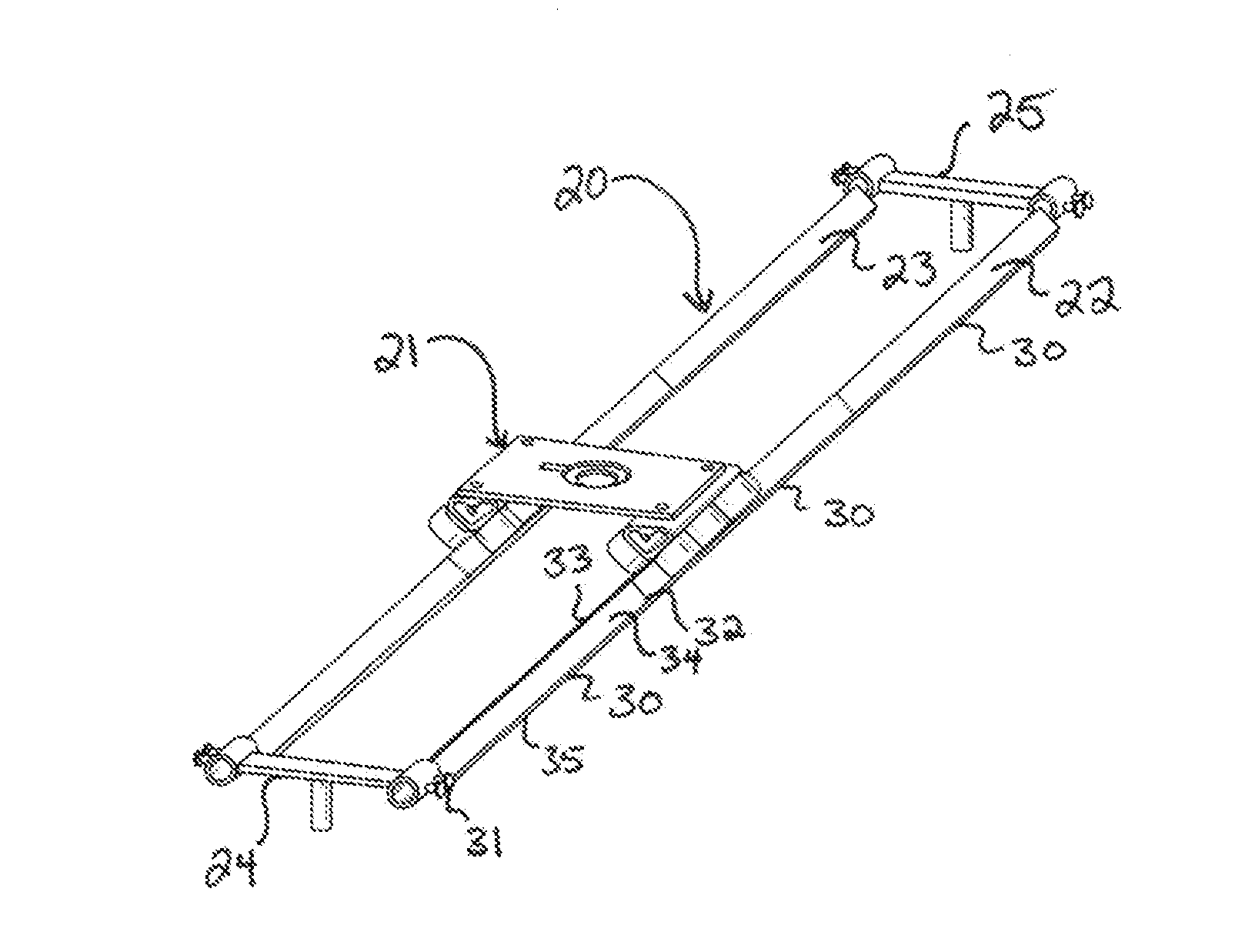
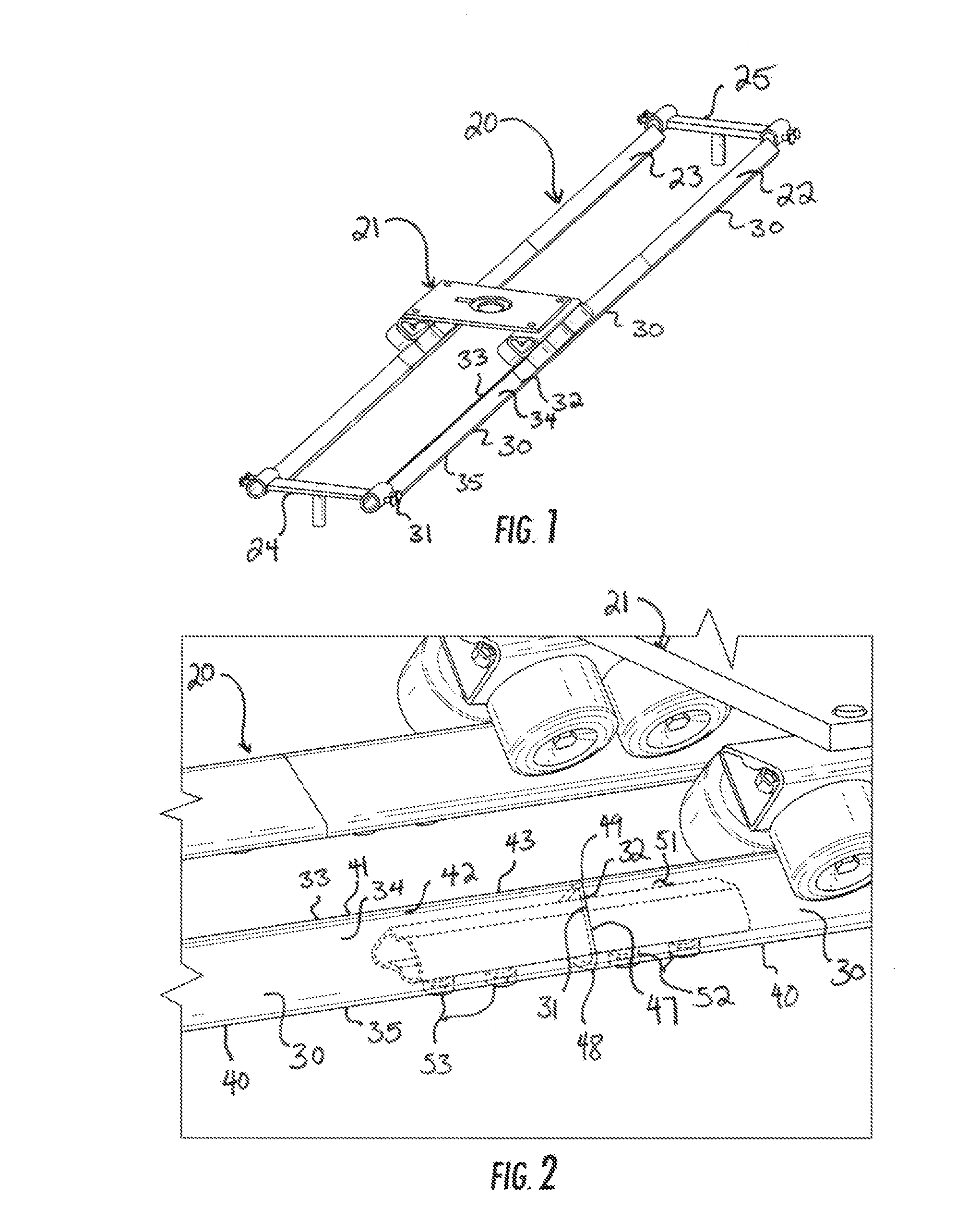
[0016]Reference now is made to the drawings, in which the same reference characters are used throughout the different figures to designate the same elements. FIG. 1 illustrates a camera dolly track assembly 20 constructed and arranged according to the principle of the invention, and carrying a dolly 21 for supporting a camera. The track assembly 20 includes two opposed, spaced-apart rails 22 and 23 extending between two opposed base assemblies 24 and 25. The rails 22 and 23 provide a smooth rolling surface for carrying the dolly 21 to ensure that a camera supported on the dolly 21 moves without interruption or disturbance, thus providing a smooth filming environment.

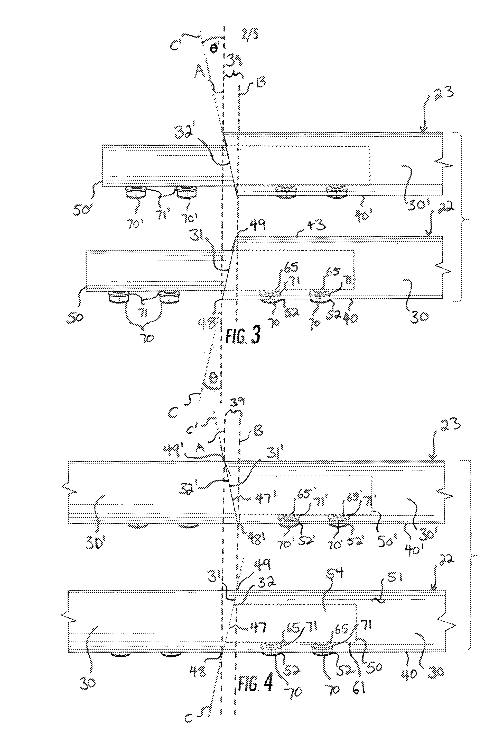
[0017]The rails 22 and 23 are identical in every respect, other than location and orientation, and as such, only the rail 22 will be described, with the understanding that the discussion of the rail 22 applies equally to the rail 23, but for location and orientation characteristics which are separately described. Further...


PUM


Abstract

A support for a camera dolly comprising spaced-apart first and second rails comprised of longitudinal rail members. The first rail has a first seam between its rail members, and the second rail has a second seam between its rail members. The first seam in the first rail is directly opposed from a corresponding second seam in the second rail. The first and second seams have first and second leading edges formed at crowns on the first and second rails, and the leading edge of the first seam is offset longitudinally with respect to the leading edge of the corresponding second seam.

Description

CROSS-REFERENCE TO RELATED APPLICATIONS[0001]This application claims the benefit of U.S. Provisional Application No. 61 / 808,408, filed Apr. 4, 2013, which is hereby incorporated by reference.FIELD OF THE INVENTION[0002]The present invention relates generally to camera equipment, and more particularly to tracks for supporting and guiding camera equipment.BACKGROUND OF THE INVENTION[0003]Video cameras, such as those used in professional media production settings, are highly sensitive pieces of equipment that must frequently be moved during filming to capture specific cinematographic shots. Video cameras respond to the slightest movement, and often do so in uncertain or undesirable ways. For that reason, the motion picture industry has developed many techniques and tools for stabilizing a camera during motion to reduce the undesirable effects of ancillary movements.[0004]The motion picture industry has produced numerous types of tracks for moving a video camera smoothly from a first po...

Claims


Application Information

Patent Timeline
Patent Type & Authority Applications(United States)
IPC IPC(8): E01B5/02B61B13/00E01B5/16
CPCE01B5/02B61B13/00E01B5/16E01B23/02F16M11/043F16M11/425B61B3/00G03B17/561
Inventor HALL, MICHAEL W.
Owner AZGRIP COM
Why Eureka
Try Eureka