System for positioning and drilling in cabinet, drawer and shelf hardware
What is Al technical title?
Al technical title is built by PatSnap Al team. It summarizes the technical point description of the patent document.
a technology for drawers and shelves, applied in the field of systems, can solve the problems of fixed construction of current tools and insufficient flexibility for work pieces of different configurations
Active Publication Date: 2015-01-15
FRICK JOHN REID
View PDF5 Cites 29 Cited by
Summary
Abstract
Description
Claims
Application Information
AI Technical Summary
This helps you quickly interpret patents by identifying the three key elements:
Problems solved by technology
Method used
Benefits of technology
[0005]The present invention is directed to a system for positioning and drilling in cabinet, drawer, and shelf hardware components. The system generally comprises a self-centering ruler having a zero mid-point and graduated measurement markings extending to each side of the zero mid-point toward opposite ends of the self-centering ruler. A channel is disposed along a length of the self-centering ruler. The channel has a generally T-shaped cross-section and is configured so as to slidingly receive a head of a securing bolt. When the head of the securing bolt is received in the channel, a stem of the securing bolt extends out of an opening in the channel, which is on the same side or face of the ruler as the measurement markings. The system also includes a jig template having an adjustment slot configured to receive the stem of the securing bolt extending from the opening of the channel. A tightening knob is configured to securingly engage the stem of the securing bolt so as to secure the jig template between the tightening knob and the self-centering ruler.
Problems solved by technology
Some of these tools, templates, guides, and jigs are adjustable or fixed and / or have limited use and some require the use of a separate measuring tape or ruler either prior to or during use to set the hole pattern.
Furthermore, the current tools have a fixed construction that does not permit sufficient flexibility with work pieces of different configurations.
Method used
Image
Click on the blue label to locate the original text in one second.
Reading with bidirectional positioning of images and text.
Examples
Embodiment Construction
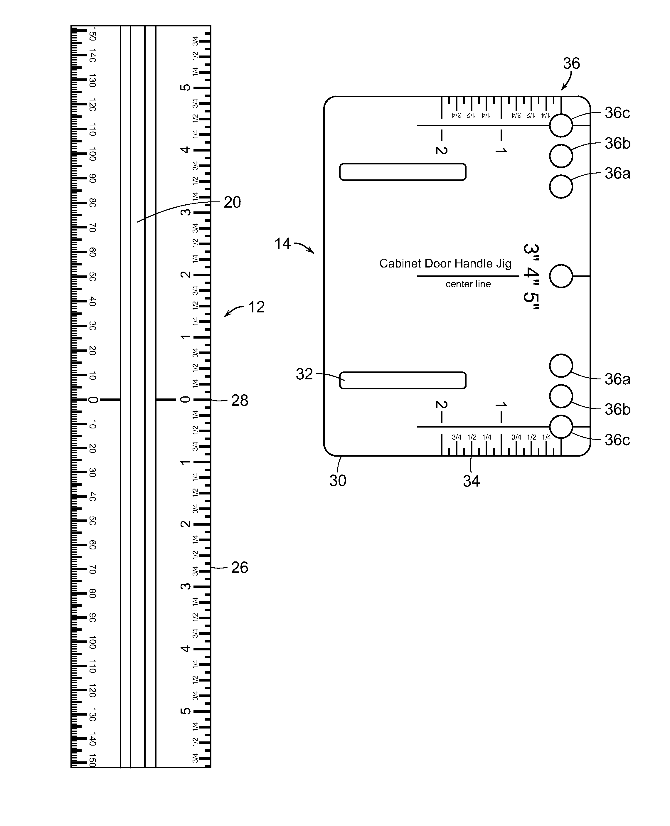
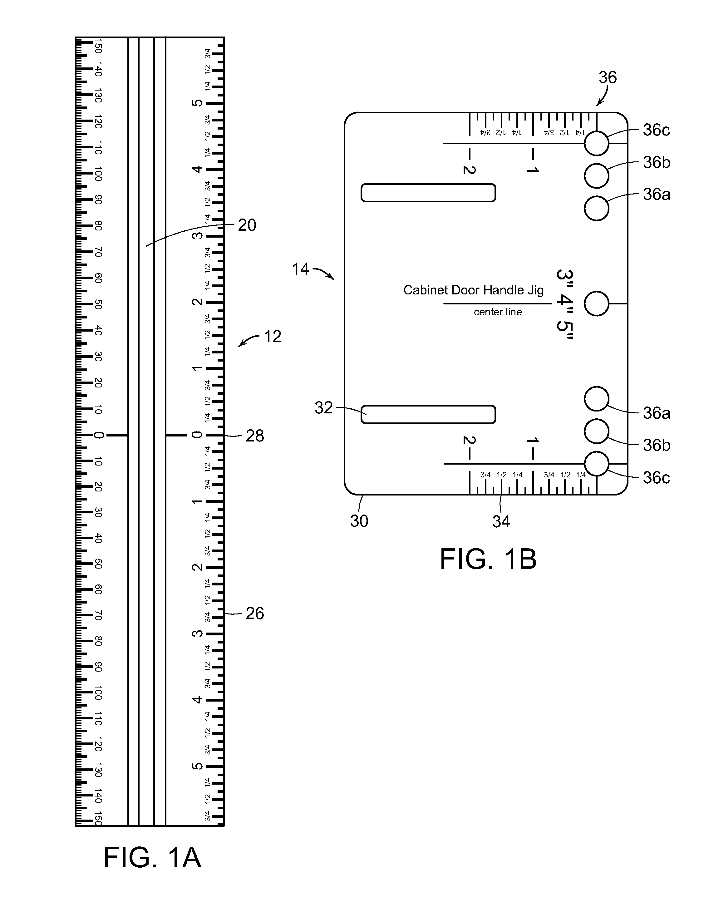
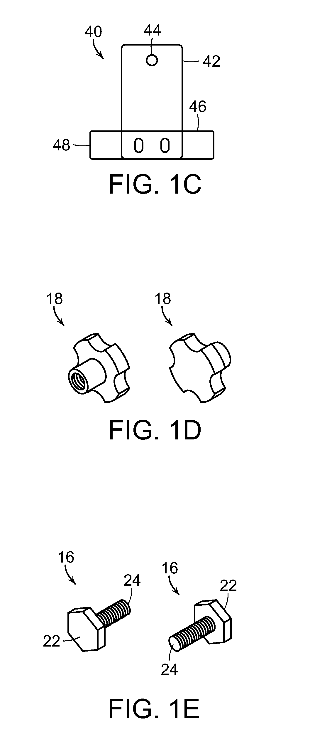
[0043]The present invention is directed to a system for positioning and drilling holes and other features in cabinet components. Specifically, the system 10 comprises a slotted ruler, generally referred to by reference numeral 12, and a jig, generally referred to by reference numeral 14. The system 10 also includes bolts 16 and tightening knobs 18 for securing the jig 14 to the slotted ruler 12.
[0044]Various embodiments of the system 10 generally comprise each of these components. The variations between each of the embodiments may comprise slotted rulers 12 of different sizes or forms and jigs 14 of different configurations, as shown in various embodiments illustrated in FIGS. 1A, 1B, and 2A through 9B. Similarly numbered figures, i.e., FIGS. 2A, 2B, and 2C, illustrate components of one particular embodiment of a kit or system 10. The various embodiments may also include additional components, i.e., stops (FIG. 1C), knobs (FIG. 1D), and bolts (FIG. 1E), as described herein.
[0045]Thr...
PUM
Property
Measurement
Unit
lengths
aaaaa
aaaaa
lengths
aaaaa
aaaaa
length
aaaaa
aaaaa
Abstract
A system for positioning and drilling in cabinet, drawer, and shelf hardware components generally having a self-centering ruler and a jig template. The ruler has a zero mid-point and graduated measurement markings extending to each side of the zero mid-point toward opposite ends. A channel is disposed along a length of the ruler and has a generally T-shaped cross-section and is configured to slidingly receive a head of the securing bolt. The jig template has an adjustment slot configured to receive a stem of the securing bolt extending from an opening of the channel. A tightening knob securingly engages the stem of the securing bolt so as to secure the jig template between the tightening knob and the self-centering ruler.
Description
RELATED APPLICATION[0001]This application claims the benefit of U.S. Provisional Application No. 61 / 843,795, filed on Jul. 8, 2013.BACKGROUND OF THE INVENTION[0002]The present invention relates generally to a system for easily and precisely positioning hardware in cabinets, drawers, bookcases and similar work pieces. More particularly, the system is for positioning and drilling holes or cups in components, such as, drawers and doors for handles and knobs, doors for hinges, side panels for drawer guides, hinges, clips or dowels, and adjustable shelves.[0003]Presently, there are various tools, templates, guides and jigs on the market to locate and drill holes in cabinet drawers, doors and side panels, as well as various tools, templates, guides and jigs to locate and drill holes in other work pieces. Some of these tools, templates, guides, and jigs are adjustable or fixed and / or have limited use and some require the use of a separate measuring tape or ruler either prior to or during u...
Claims
Application Information
Patent Timeline
Application Date:The date an application was filed.
Publication Date:The date a patent or application was officially published.
First Publication Date:The earliest publication date of a patent with the same application number.
Issue Date:Publication date of the patent grant document.
PCT Entry Date:The Entry date of PCT National Phase.
Estimated Expiry Date:The statutory expiry date of a patent right according to the Patent Law, and it is the longest term of protection that the patent right can achieve without the termination of the patent right due to other reasons(Term extension factor has been taken into account ).
Invalid Date:Actual expiry date is based on effective date or publication date of legal transaction data of invalid patent.
Patent Type & Authority Applications(United States)