Coin dispensing apparatus
a coin dispensing and apparatus technology, applied in coin counters, coin/paper handlers, instruments, etc., can solve the problems of large inner forces of the rotary disk and its related parts, deformation of the durability of the coin dispensing apparatus, and inability to selectively eject coins, etc., to achieve excessive dispensing or payout
- Summary
- Abstract
- Description
- Claims
- Application Information
AI Technical Summary
Benefits of technology
Problems solved by technology
Method used
Image
Examples
first embodiment
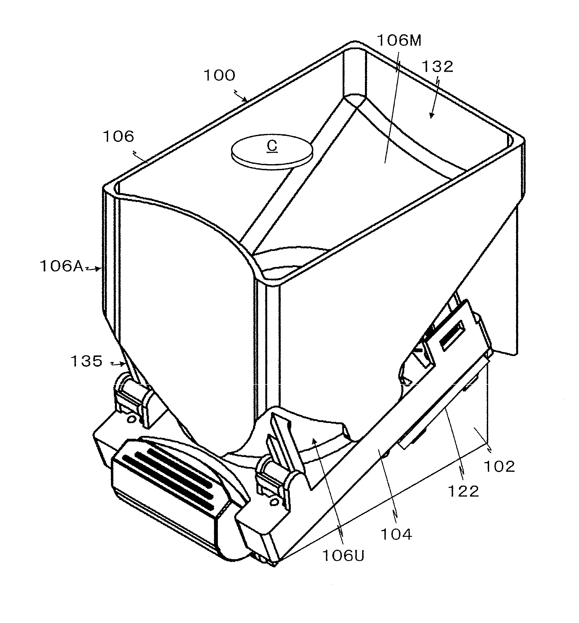
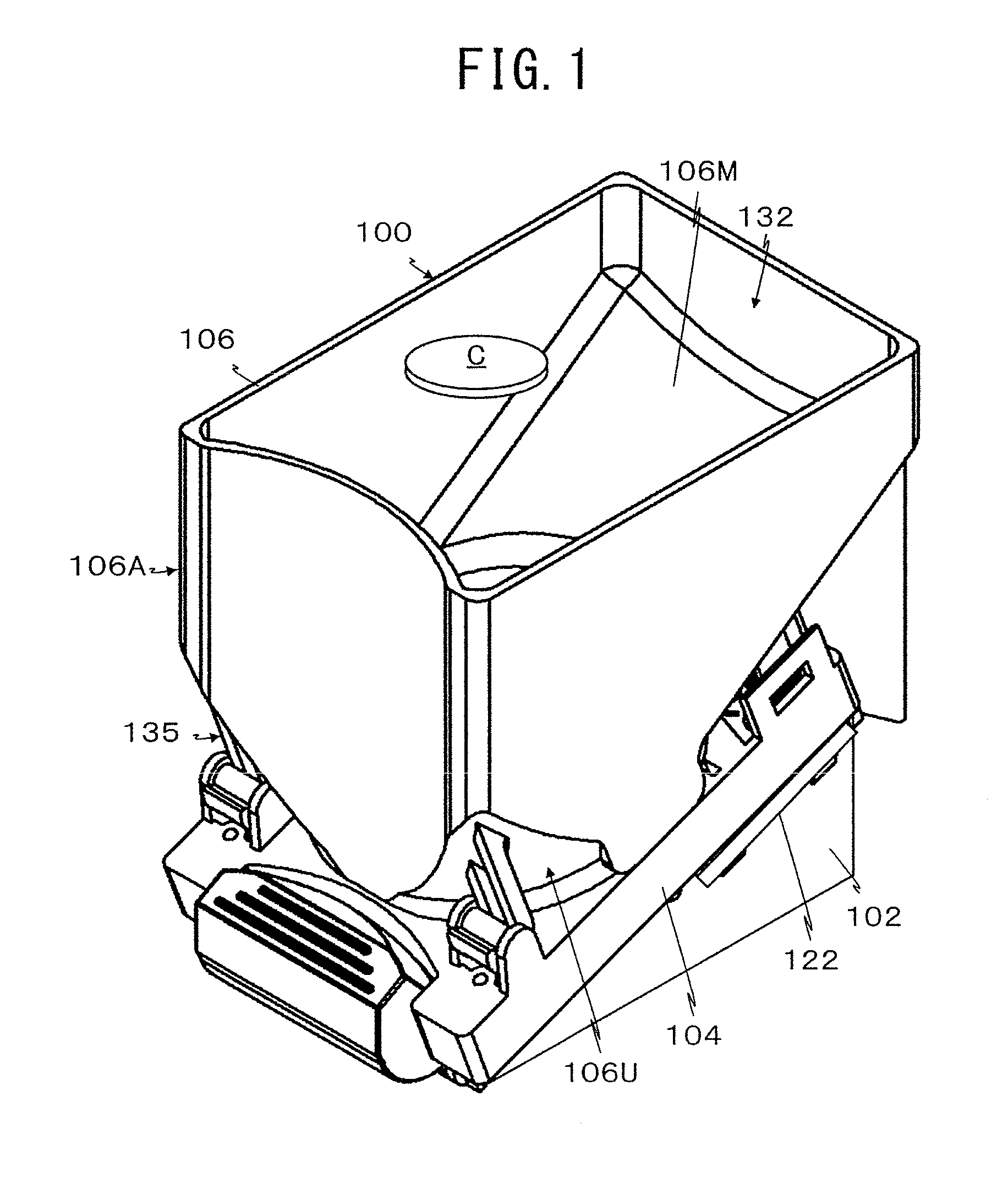
[0063]A coin dispensing apparatus 100 according to a first embodiment of the present invention is shown in FIGS. 1 to 17. The apparatus 100 has the function of separating coins C that have been randomly collected and then, dispensing the coins C one by one.
[Overall Structure of Coin Dispensing Apparatus]
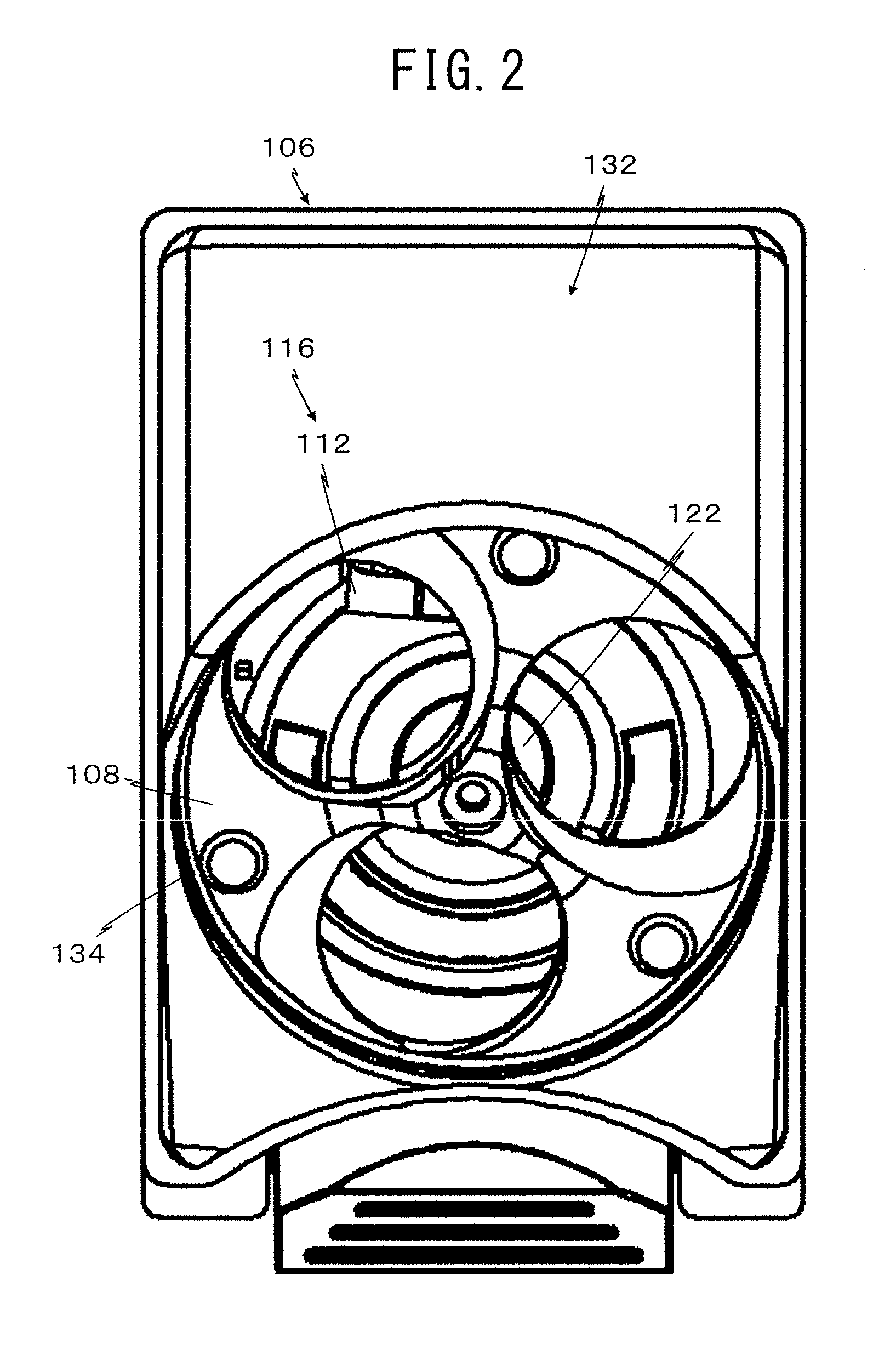
[0064]As shown in FIGS. 1 to 3, the coin dispensing apparatus 100 according to the first embodiment comprises a frame 102, a base 104, a coin storing bowl or coin container 106, a rotary disk 108, a dispensing opening 110, a guide pin or guide member 112, a dispensing passage 114, an ejecting device 116, a coin sensor 118, a stopper 120, and a control circuit 122. The frame 102, the base 104, the coin storing bowl 106, the rotary disk 108, the dispensing opening 110, the dispensing passage 114, and the coin sensor 118 have known structures, respectively. The feature of the present invention relates to the guide pin 112 and the stopper 120.
[0065]Here, the base 104 (and the frame 102) ...
second embodiment
[0244]Next, a coin dispensing apparatus 300 according to a second embodiment of the present invention will be explained below with reference to FIGS. 18A, 18B, 19A and 19B.
[0245]Unlike the aforementioned coin dispensing apparatus 100 according to the first embodiment, the coin dispensing apparatus 300 according to the second embodiment is obtained by applying the present invention to a coin dispensing apparatus having a fixed member 322 and an ejecting roller 324. As explained later, the fixed member 322 and the ejecting roller 324 constitute an ejecting device 320.
[0246]In the following description, the explanation about the same structure as that of the first embodiment will be omitted by giving the same reference numerals to the same or equivalent elements for the sake of simplification of description.
[0247]Similar to the guide pin 112 used in the coin dispensing apparatus 100 of the above-described first embodiment, a guide pin 302 used in the coin dispensing apparatus 300 is pr...
third embodiment
[0266]FIG. 20 shows a coin dispensing apparatus 500 according to a third embodiment of the present invention.
[0267]The coin dispensing apparatus 500 according to the third embodiment is configured to make it possible to dispense four types of coins C, i.e., 10 yen, 100 yen, 50 yen and 500 yen, where the four coin dispensing apparatuses 100 according to the aforementioned first embodiment are combined together.
[0268]In the coin dispensing apparatus 500 according to the third embodiment, as shown in FIG. 20, the four coin dispensing apparatuses 100 according to the first embodiment are fixed in line on the upper plate 503 of a chassis 501. The four rotary disks 108 of the four apparatuses 100 are driven by a single common driving device 504 instead of individually driving the four disks 108 by the electric motors 124 as used in the first embodiment.
[0269]The common driving device 504 comprises an electric motor 505, a reduction gear device 506 for reducing the rotation speed of the mo...
PUM
 Abstract
Description
Claims
Application Information
 - R&D
- Intellectual Property
- Life Sciences
- Materials
- Tech Scout
- Unparalleled Data Quality
- Higher Quality Content
- 60% Fewer Hallucinations
Browse by: Latest US Patents, China's latest patents, Technical Efficacy Thesaurus, Application Domain, Technology Topic, Popular Technical Reports.
© 2025 PatSnap. All rights reserved.Legal|Privacy policy|Modern Slavery Act Transparency Statement|Sitemap|About US| Contact US: help@patsnap.com


