Tube Bending Machine With Reversible Clamp Assembly

a tube bending machine and clamp assembly technology, which is applied in the direction of metal-working feeding devices, manufacturing tools, transportation and packaging, etc., can solve the problems of clamping blocks that cannot feed at least a portion of the tube, warping, deformation, etc., and the clamping block is incapable of swinging the unsupported first end of the tub

Active Publication Date: 2015-05-21
HUGHES JR ROBERT KYLE
View PDF6 Cites 28 Cited by
  • Summary
  • Abstract
  • Description
  • Claims
  • Application Information

AI Technical Summary

Problems solved by technology

However, this type of bending operation presents a number of problems.
However, once the first bend in the tube proximate the first end of the tube is formed, the operation of forming subsequent bends in the tube toward the second end of the tube can result in drastic swinging of the unsupported first end of the tube, due to the geometry of the previous bend(s) and the extension of the first end of the tube beyond the forming die.
If the first end of the tube is not properly supported, this can result in warping, deformation, or other inaccuracies in the geometry of the finished tube product.
In most rotary tube bender designs, the clamping block is incapable of feeding at least a portion of the tube nearest the second end through the interface of the forming die and the counter die.
Thus, in previous prior art rotary tube bender designs, it is difficult to perform a bend at or near the second end of the tube without also disconnecting the second end of the tube from the clamping block, thereby sacrificing stability of the tube within the rotary tube bender and potentially allowing inconsistency of measurement of rotation of the tube about the feeding direction during multiple bending processes.

Method used


Image

  • Tube Bending Machine With Reversible Clamp Assembly
  • Tube Bending Machine With Reversible Clamp Assembly
  • Tube Bending Machine With Reversible Clamp Assembly

Examples


Embodiment Construction

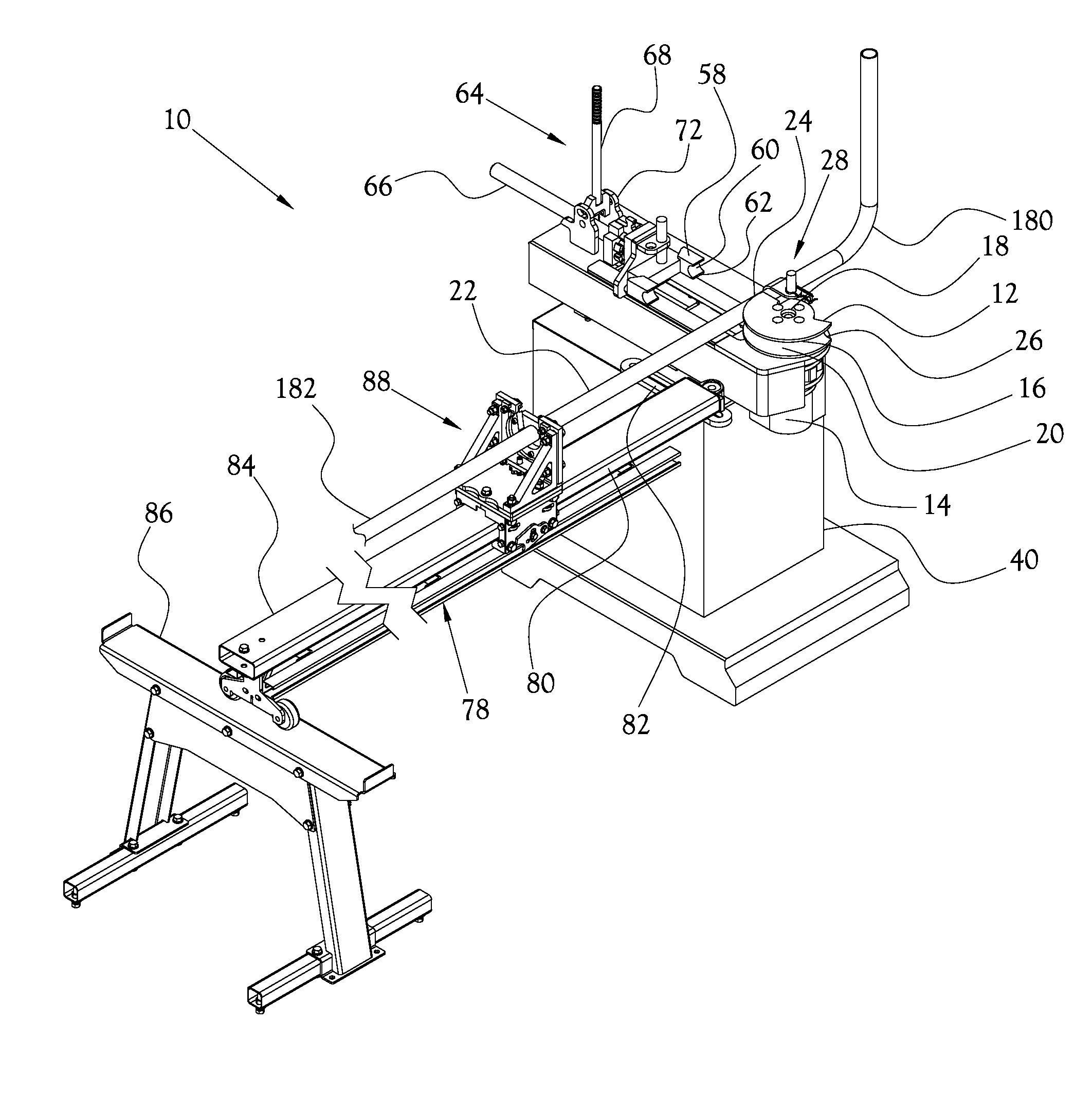
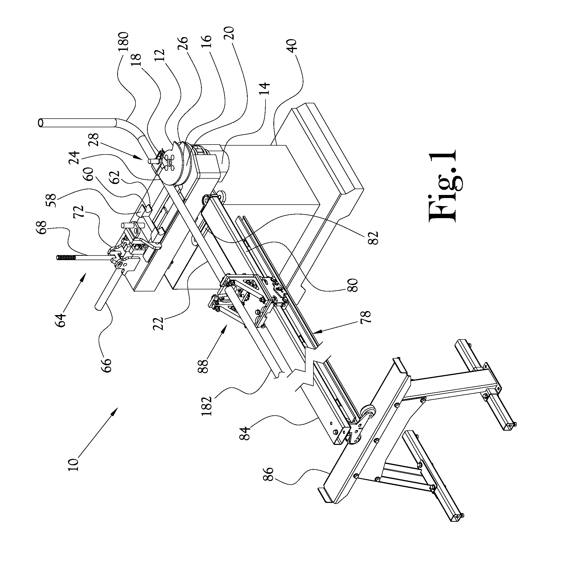
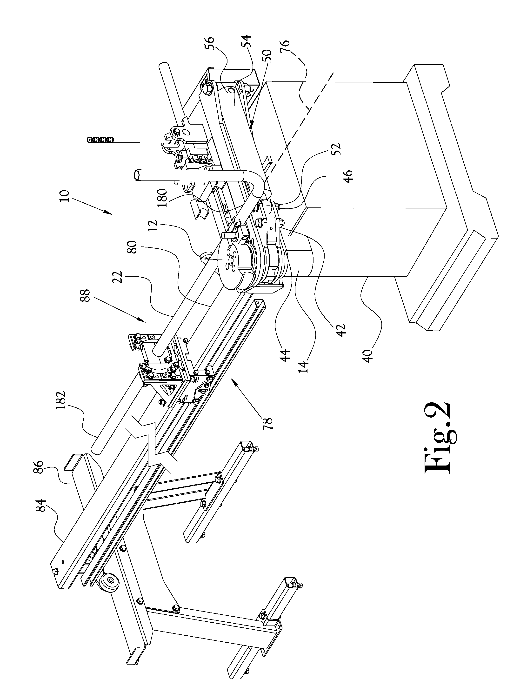
[0026]Reference will now be made to the example embodiments of the present general inventive concept, examples of which are illustrated in the accompanying drawings and illustrations. The example embodiments are described herein in order to explain the present general inventive concept by referring to the figures. The following detailed description is provided to assist the reader in gaining a comprehensive understanding of the structures and fabrication techniques described herein. Accordingly, various changes, modification, and equivalents of the structures and fabrication techniques described herein will be suggested to those of ordinary skill in the art. The progression of fabrication operations described are merely examples, however, and the sequence type of operations is not limited to that set forth herein and may be changed as is known in the art, with the exception of operations necessarily occurring in a certain order. Also, description of well-known functions and construc...


PUM

PropertyMeasurementUnit
lengthaaaaaaaaaa
perimeteraaaaaaaaaa
shapeaaaaaaaaaa

Abstract

A tube bending machine for bending a length of a tubular workpiece and an associated tube feeder assembly are disclosed. The tube feeder assembly has a carriage assembly slidably mounted along a rail. A clamp assembly is reversibly mounted to and carried by the carriage assembly. The clamp assembly is adapted to be releasably secured to the workpiece. The clamp assembly and carriage assembly are configurable to align the workpiece central axis along the rail, whereby sliding of the carriage assembly with the workpiece mounted in the clamp assembly carries the workpiece along the rail.

Description

CROSS-REFERENCE TO RELATED APPLICATIONS[0001]This application claims the benefit of U.S. Provisional Patent Application Ser. No. 61 / 904,023, filed on Nov. 14, 2014, which is incorporated herein in its entirety by reference.STATEMENT REGARDING FEDERALLY-SPONSORED RESEARCH OR DEVELOPMENT[0002]Not ApplicableBACKGROUND OF THE INVENTION[0003]1. Field of Invention[0004]The invention relates to tube bending machines, and particularly, to a reversible clamp assembly for a tube bending machine, and a tube bending machine incorporating a reversible assembly.[0005]2. Description of the Related Art[0006]Numerous buildings, construction sites, manufacturing plants, machine shops, and the like use bent tubes, pipes, bars, rods, or the like (hereinafter, collectively, “tubes”) to produce a variety of items such as hand rails, scaffolding, automotive parts, or other fabricated metal products. In the manufacture and forming of tubes, several types of tube bending machines are known which are useful ...

Claims


Application Information

Patent Timeline
Patent Type & Authority Applications(United States)
IPC IPC(8): B21D43/00B21D7/08
CPCB21D7/085B21D43/006B21D7/024
Inventor HUGHES, JR., ROBERT KYLE
Owner HUGHES JR ROBERT KYLE
Why Eureka
Try Eureka