Maximum Security/Maximum Versatility Ball Mount Assembly

a technology of ball mounts and accessories, applied in the field of maximum security/maximum versatility of ball mounts, can solve the problems of inconvenient placement or easy access, interference with the proper fastening of safety chains, and potential safety concerns

Inactive Publication Date: 2015-05-21
COLUMBIA JOHN R
View PDF15 Cites 10 Cited by
  • Summary
  • Abstract
  • Description
  • Claims
  • Application Information

AI Technical Summary

Benefits of technology

[0026]It is an aspect of the invention to provide improved elements and arrangements thereof for the pur...

Problems solved by technology

However, in most cases, most of the pins are designed to be inserted through the apertures in the receiver which, in the majority of cases, are not conveniently located or easily accessible.
In addition, when inserted, the pin generally is located directly above or in front of the receiver's safety chain connection loop/ring mounts and oftentimes components of the protruded hitch pin or locking hitch pin interfere with the proper fastening of safety chains.
Without adequate clearance to fasten safety chains to the receiver using properly sized quick links, S-hooks, snap hooks, grab hooks, latch hooks or the like, there may be a tendency to utilize undersized links or hooks to attach the chains causing a potential safety concern.
Additionally, based upon the location of the receiver's apertures and owing to the inability to see when the ball mount and receiver apertures are aligned for pinning, people will frequently use a finger to feel when the holes are aligned, oftentimes resulting in pinched fingers.
While the O-rings are effective in keeping foreign particles out of the locking mechanism, they often make it more difficult to determine with certainty that the lock is in fact engaged to the hitch pin.
Ensuring the lock is engaged to the hitch pin is increasingly more difficult to determine when the receiver apertures ar...

Method used


Image

  • Maximum Security/Maximum Versatility Ball Mount Assembly
  • Maximum Security/Maximum Versatility Ball Mount Assembly
  • Maximum Security/Maximum Versatility Ball Mount Assembly

Examples


Embodiment Construction

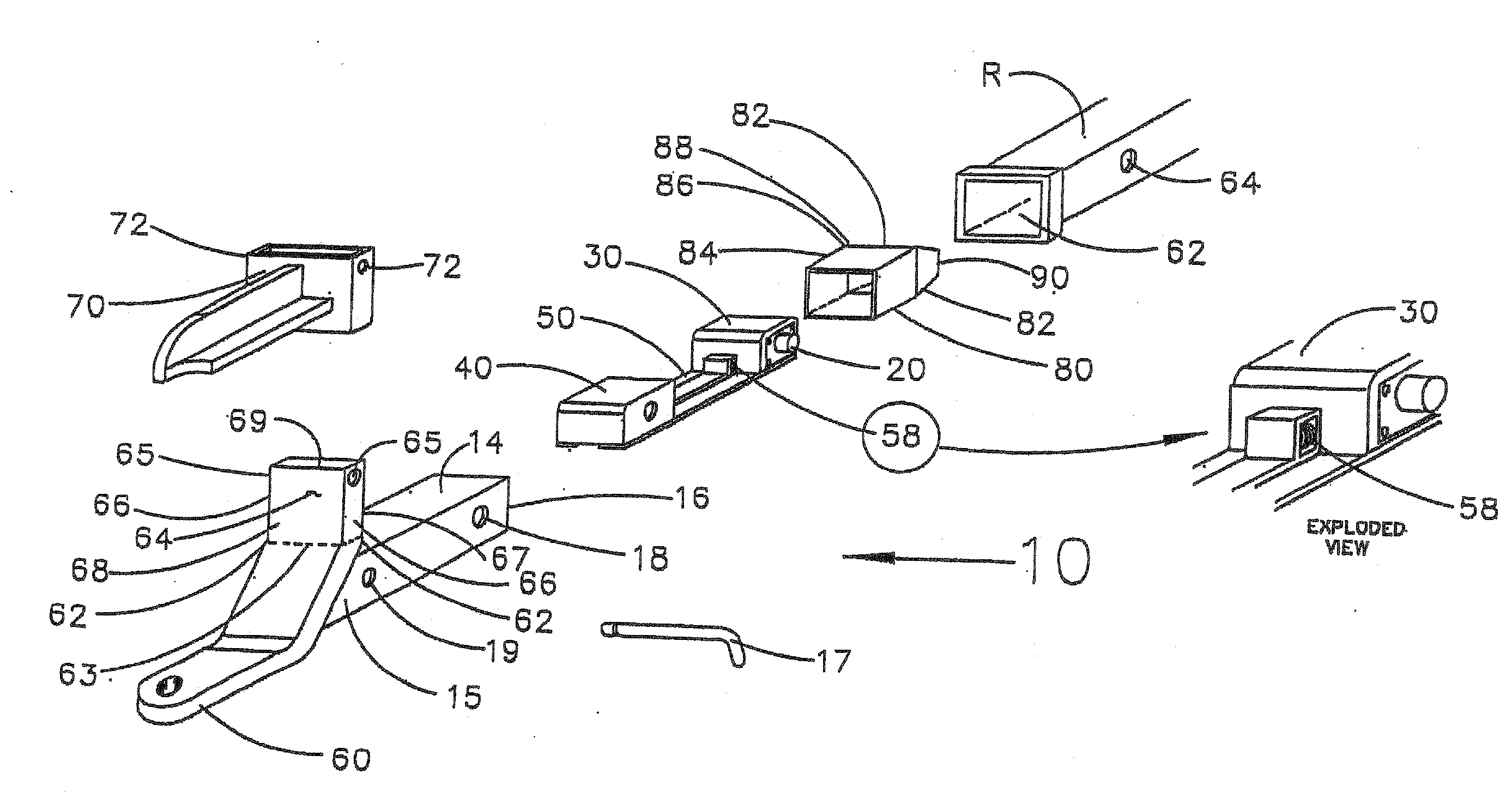
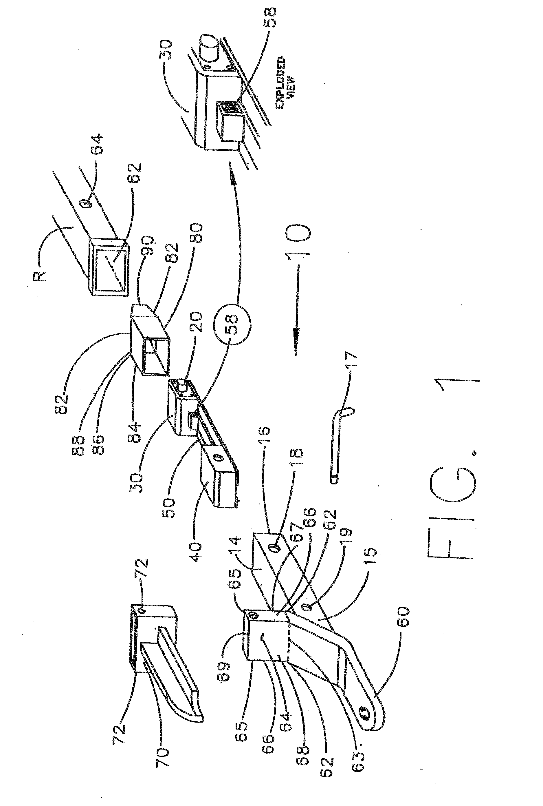
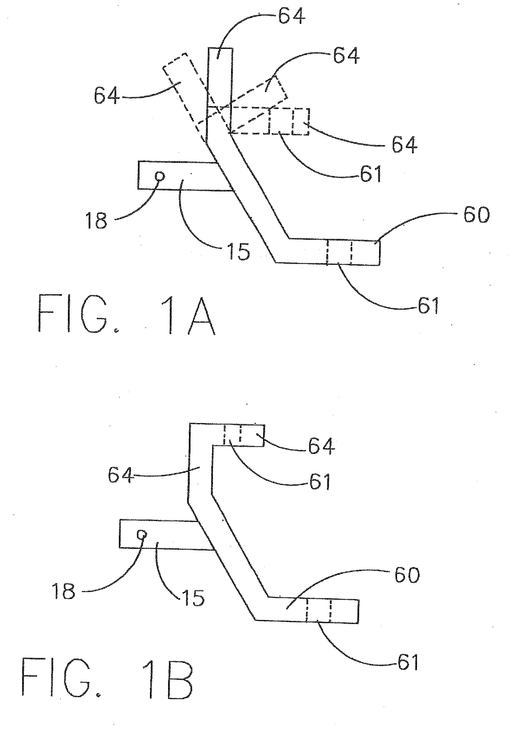
[0096]As used herein, spatial or directional terms, such as “top,”“bottom,”“left,”“right,”“over,”“under,”“front,”“rear,” and the like, relate to the invention as it is shown in the drawing figures. However, it is to be understood that the invention can assume various alternative orientations, and, accordingly, such terms are not to be considered as limiting. Further, all numbers expressing dimensions, physical characteristics, and so forth, used in the specification, figures, and claims are to be understood as being modified in all instances by the term “about.” Accordingly, unless indicated to the contrary, the numerical values set forth in the following specification, figures, and claims can vary depending upon the desired properties sought to be obtained by the present invention. At the very least, and not as an attempt to limit the application of the doctrine of equivalents to the scope of the claims, each numerical parameter should at least be construed in light of the number o...


PUM

PropertyMeasurementUnit
Diameteraaaaaaaaaa

Abstract

A hitch accessory retaining device includes a pair of opposed engagement pins and a biasing device. When positioned within a shank body, the engagement pins are slidable within shank pinning apertures and are normally urged in outward, extended positions by the biasing device. When biased outwardly, a portion of each engagement pin extends outwardly from and projects beyond a shank sidewall while an additional portion of each engagement pin is retained within the shank body. A portion of the biasing device contacts, is attached to, or is part of, the engagement pins. The normally outwardly biased engagement pins are biasable inwardly to a retracted position within the shank pinning apertures to a position wherein the outward ends of the engagement pins are flush with the outward sides of shank sidewalls.

Description

CROSS REFERENCE TO RELATED PATENT APPLICATIONS[0001]This application is a continuation-in-part of U.S. application Ser. No. 12 / 486,052, filed Jun. 17, 2009 (now U.S. Pat. No. 8,840,130), which claimed the benefit of U.S. Provisional Application No. 61 / 073,100, filed on Jun. 17, 2008, and which was a continuation-in-part of U.S. application Ser. No. 12 / 025,990, filed Feb. 5, 2008, which claimed the benefit of U.S. Provisional Application No. 60 / 899,609, filed on Feb. 5, 2007, and U.S. Provisional Application No. 60 / 993,781, filed on Sep. 14, 2007, and which also was a continuation-in-part of U.S. application Ser. No. 11 / 372,748, filed on Mar. 10, 2006, and U.S. application Ser. No. 11 / 732,117, filed on Apr. 2, 2007. All of the above applications are herein incorporated by reference in their entirety.BACKGROUND OF THE INVENTION[0002]1. Field of the Invention[0003]The present invention relates generally to trailer hitch accessories, and more particularly, to an improved ball mount asse...

Claims


Application Information

Patent Timeline
IPC IPC(8): B60D1/60B60D1/06
CPCB60D1/06B60D1/60B60D1/07B60D1/52B60D1/58Y10T29/49876
Inventor COLUMBIA, JOHN R.
Owner COLUMBIA JOHN R
Why Eureka
Try Eureka