Mask and mask assembly

a mask and assembly technology, applied in the field of masks and mask assemblies, can solve the problems of difficult patterning by using a general photolithography process, and achieve the effect of improving the ease of handling

Active Publication Date: 2015-06-18
SAMSUNG DISPLAY CO LTD
View PDF2 Cites 31 Cited by
  • Summary
  • Abstract
  • Description
  • Claims
  • Application Information

AI Technical Summary

Benefits of technology

The patent describes an improvement for making it easier to handle different types of patterns while wearing a mask or face covering. This makes it more convenient for people who want to protect their health by wearing these coverings during times when they may be exposed to harmful substances or conditions.

Problems solved by technology

The technical problem addressed in this patent relates to finding ways to improve the formation of electrodes and organic light emitting layers in organic light emitting displays. These materials require complete isolation from moisture and oxygen, making traditional methods such as photolithography challenging. Mask assemblies have been developed but they suffer from deteriorating forms due to tension. This patent seeks to address these issues and provide better techniques for creating high-quality organic light emitting displays.

Method used


Image

  • Mask and mask assembly
  • Mask and mask assembly
  • Mask and mask assembly

Examples


Embodiment Construction

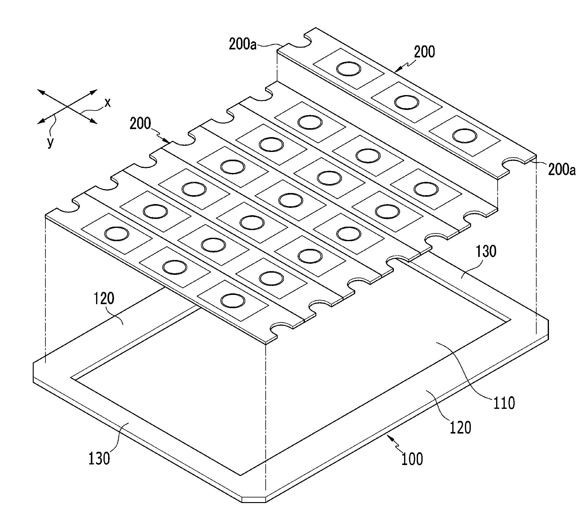
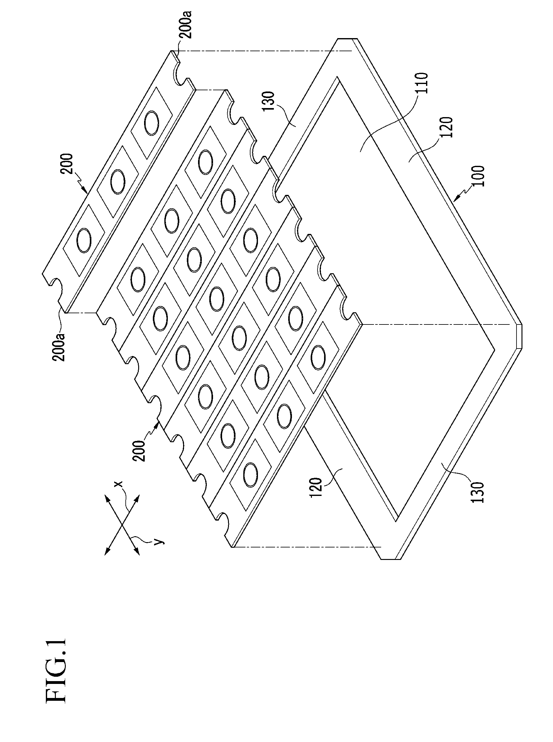
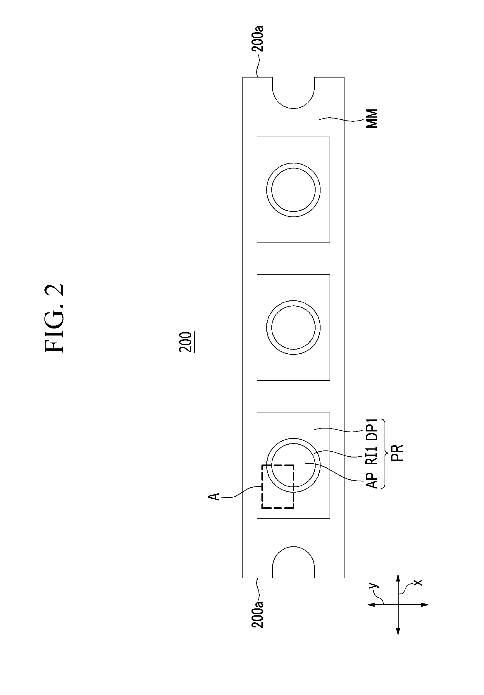
[0045]Hereinafter, exemplary embodiments of the present invention will be described in detail with reference to the accompanying drawings so that those skilled in the technical field to which the present disclosure pertains may carry out the exemplary embodiments. The present invention may be implemented in various different forms, and is not limited to the exemplary embodiment described herein.

[0046]A part irrelevant to the description will be omitted so as to clearly describe the present invention, and the same or similar elements will be designated by the same reference numerals throughout the specification.

[0047]Furthermore, in exemplary embodiments, since like reference numerals designate like elements having the same configuration, a first exemplary embodiment is representatively described, and in other exemplary embodiments, only a configuration different from the first exemplary embodiment will be described.

[0048]In addition, each configuration illustrated in the drawings is...


PUM

PropertyMeasurementUnit
Thicknessaaaaaaaaaa
Forceaaaaaaaaaa
Shapeaaaaaaaaaa

Abstract

A mask has both ends supported on a frame while tensile force is applied in a first direction. The mask includes: a mask main body having a band shape which is extended in the first direction; a plurality of active patterns spaced apart in the first direction from each other in the mask main body and having a first shape; a plurality of first ribs surrounding borders of the plurality of respective active patterns and defining a shape of the active pattern; and a plurality of first dummy patterns surrounding the plurality of first ribs, respectively, and having a second shape.

Description


Claims


Application Information

Patent Timeline
Owner SAMSUNG DISPLAY CO LTD
Why Eureka
Try Eureka