Invisible magnetic tie clip and related methods and systems

a magnetic tie clip and invisible technology, applied in the field of tie clips and tie retainers, can solve the problems of tail hanging out from behind the tie, usually too short back or “tail” of the tie, and previous tie clips were not able to solve this problem

Inactive Publication Date: 2015-07-23
KELLER ANDY
View PDF9 Cites 17 Cited by
  • Summary
  • Abstract
  • Description
  • Claims
  • Application Information

AI Technical Summary

Benefits of technology

[0016]Another object of the invention is to provide a solution to fashionably securing a tie to the body when worn.

Problems solved by technology

A common problem with men's ties, especially for taller men and for men who prefer a double Windsor knot is that the back or “tail” of the tie is usually too short to go through the keeper on the back of the front blade of the tie.
This results in the tail hanging out from behind the tie, looking very sloppy.
Previous tie clips were not able to resolve this issue as they were designed to attach to the lower part of the front blade of the tie and then to the shirt.
Others have pins or points that pierce the material on the back of the tie, potentially damaging it, or creating a point from which damage can proceed.

Method used


Image

  • Invisible magnetic tie clip and related methods and systems
  • Invisible magnetic tie clip and related methods and systems
  • Invisible magnetic tie clip and related methods and systems

Examples


Embodiment Construction

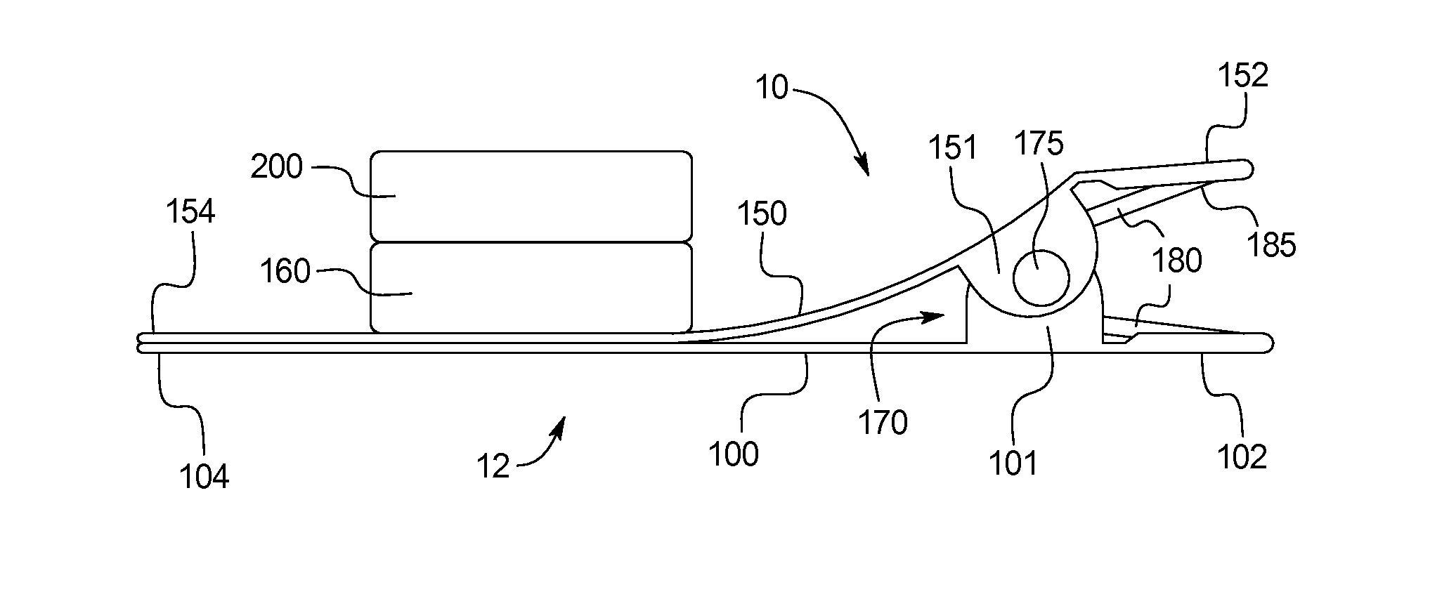
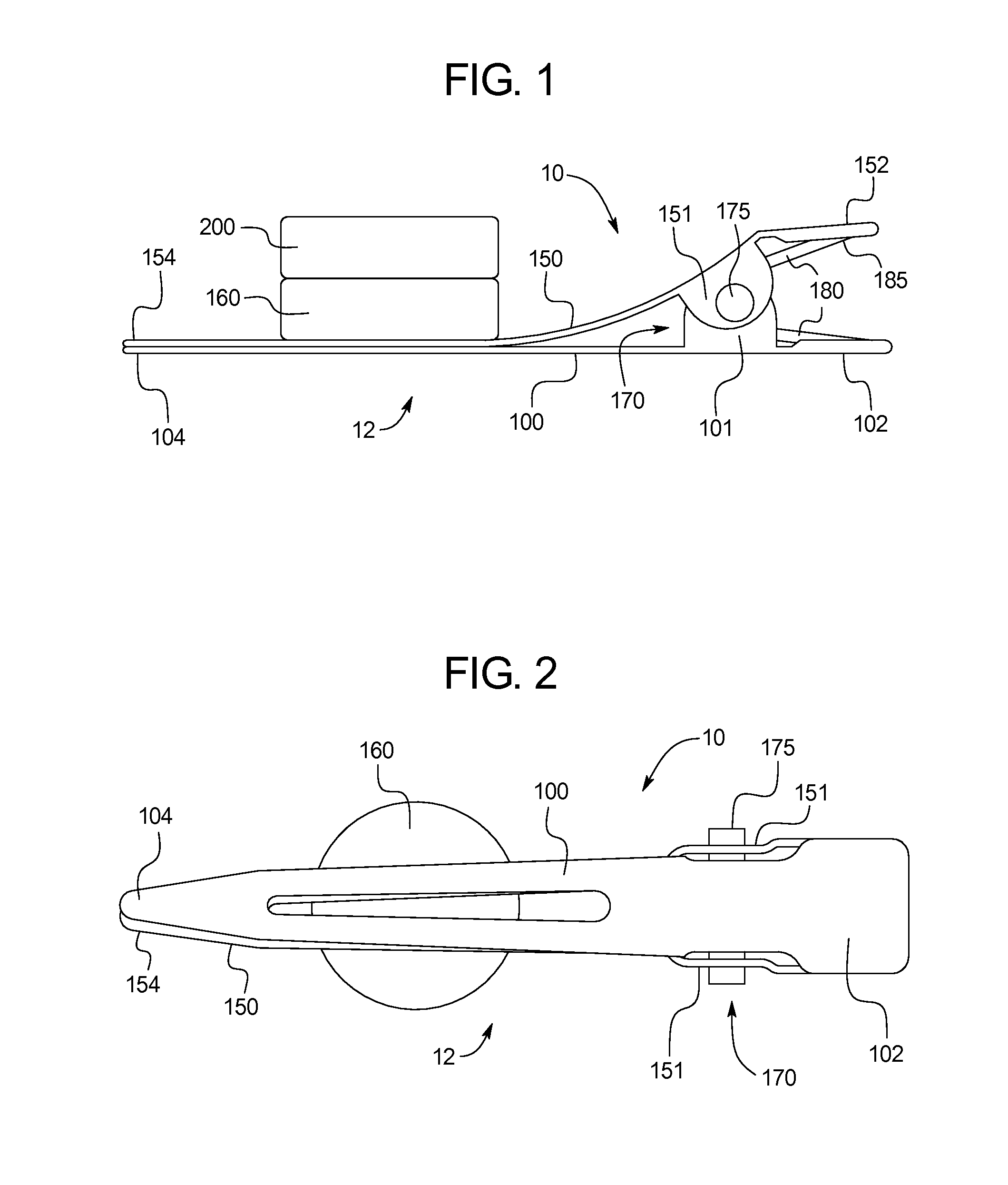
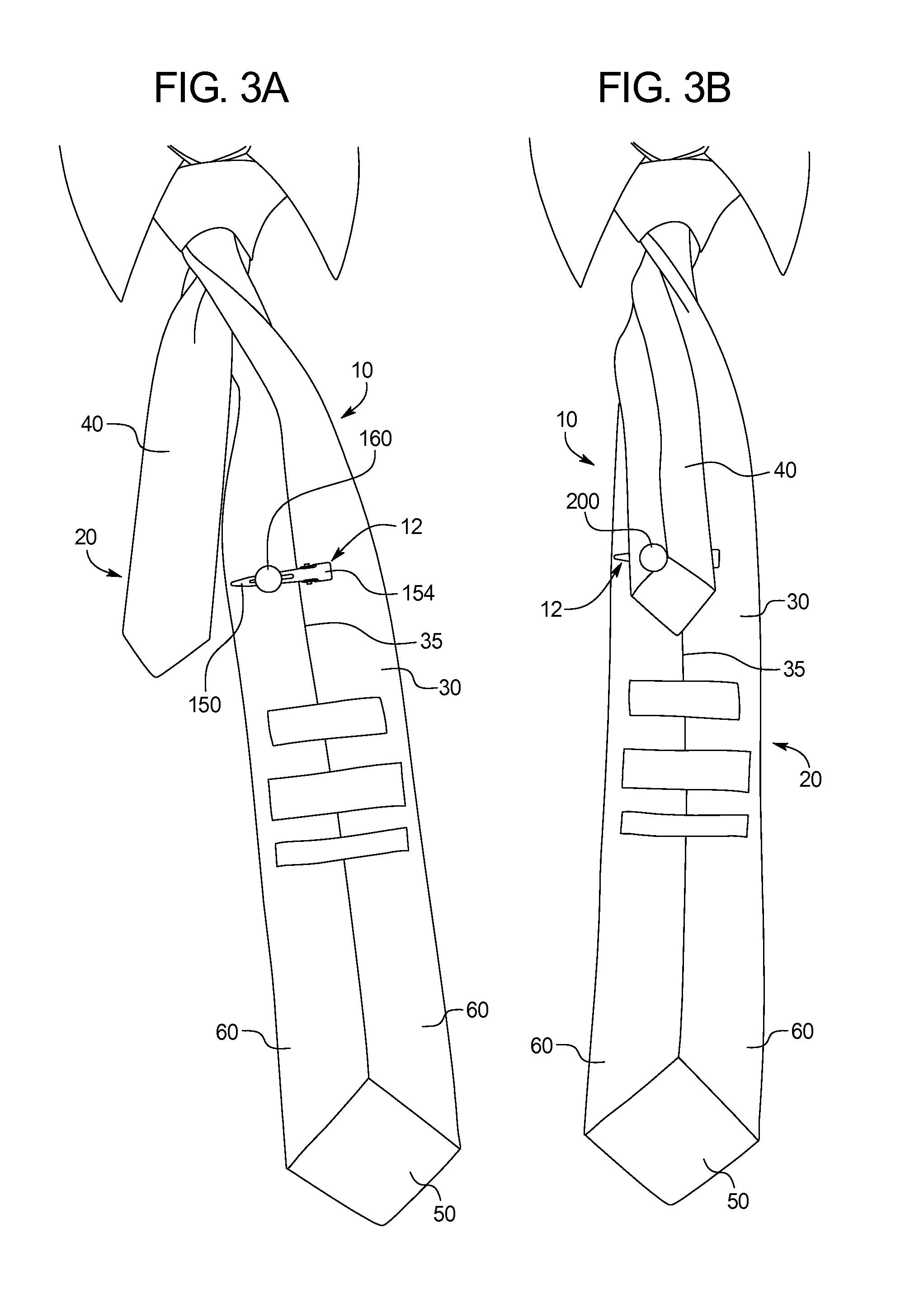
[0026]Referring to FIGS. 1, 2, and 3A and 3B, a first tie clip system 10 in accordance with the present disclosure is depicted. In the depicted embodiment, the tie clip system 10 includes tie clip 12 that may be affixed to a tied tie 20 to secure a rear blade 40 of the tie 20 to the front blade 40 of the tie 20. In some embodiments, the tie clip system 10 may be embodied in a combination of the tie 20 and the tie clip 12, and, in other embodiments, the tie clip system 10 may be embodied in a combination of the tie clip 12 and the tie 20.

[0027]Starting with FIG. 1, the tie clip 12 may include a first arm 100 which may be connected to a second arm 150 at a hinge 170. The first arm 100 and the second arm 150 may rotate with respect to each other around the hinge 170 and may be biased towards one another by a biasing element 180. In the depicted embodiment, the first and second arms 100, 150 are biased by a spring 185 that applies a separating force to handle portions 102 and 152 of the...


PUM


Abstract

A tie clip system including a tie including a front blade, wherein the front blade includes a front portion and a rear portion, wherein the front portion includes a front rear face, wherein the rear portion includes a front face and back rear face, a rear blade; and a tie clip including a first arm located between the front rear face and the front face, a second arm connected to the first arm at a hinge, wherein the second arm is located between the back rear face and the rear blade, a biasing element biasing the first arm towards contact with the second arm, a first magnetic element connected to the second arm, and a second magnetic element magnetically securing the rear blade between the first magnetic element and the second magnetic element.

Description

CROSS-REFERENCE TO RELATED APPLICATIONS[0001]This application incorporates by reference and claims the benefit of U.S. Provisional Patent Application No. 61 / 929,286 filed Jan. 20, 2014.BACKGROUND OF THE INVENTION[0002]The present subject matter relates generally to tie clips and tie retainers for tied ties. More specifically, the present invention relates to tie clips for securing the rear blade of a tie to the front blade and for securing the tie to a shirt.[0003]A common problem with men's ties, especially for taller men and for men who prefer a double Windsor knot is that the back or “tail” of the tie is usually too short to go through the keeper on the back of the front blade of the tie. This results in the tail hanging out from behind the tie, looking very sloppy.[0004]Previous tie clips were not able to resolve this issue as they were designed to attach to the lower part of the front blade of the tie and then to the shirt. Others have pins or points that pierce the material on...

Claims


Application Information

Patent Timeline
Patent Type & Authority Applications(United States)
IPC IPC(8): A44B6/00A41D25/00A41B1/08A41F1/00
CPCA44B6/00A41B1/08A41D25/00A41F1/002A44D2203/00
Inventor KELLER, ANDY
Owner KELLER ANDY
Why Eureka
Try Eureka