
Apparatus and method to monitor the occupied volume within a fixed or variable volume
- Summary
- Abstract
- Description
- Claims
- Application Information
AI Technical Summary
Benefits of technology
Problems solved by technology
Method used
Image

Examples
first embodiment
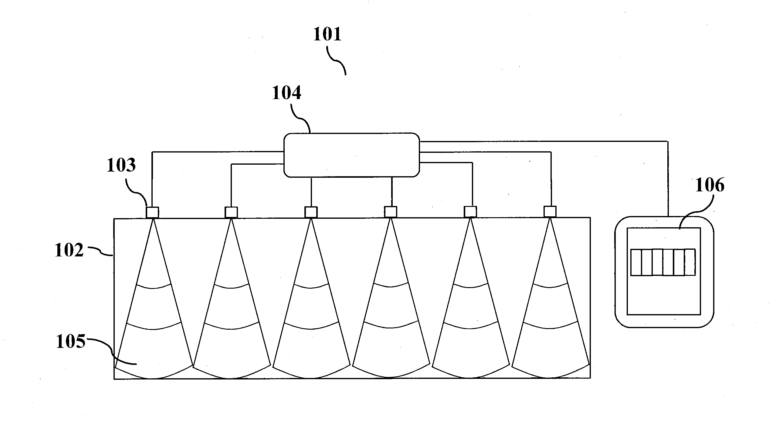
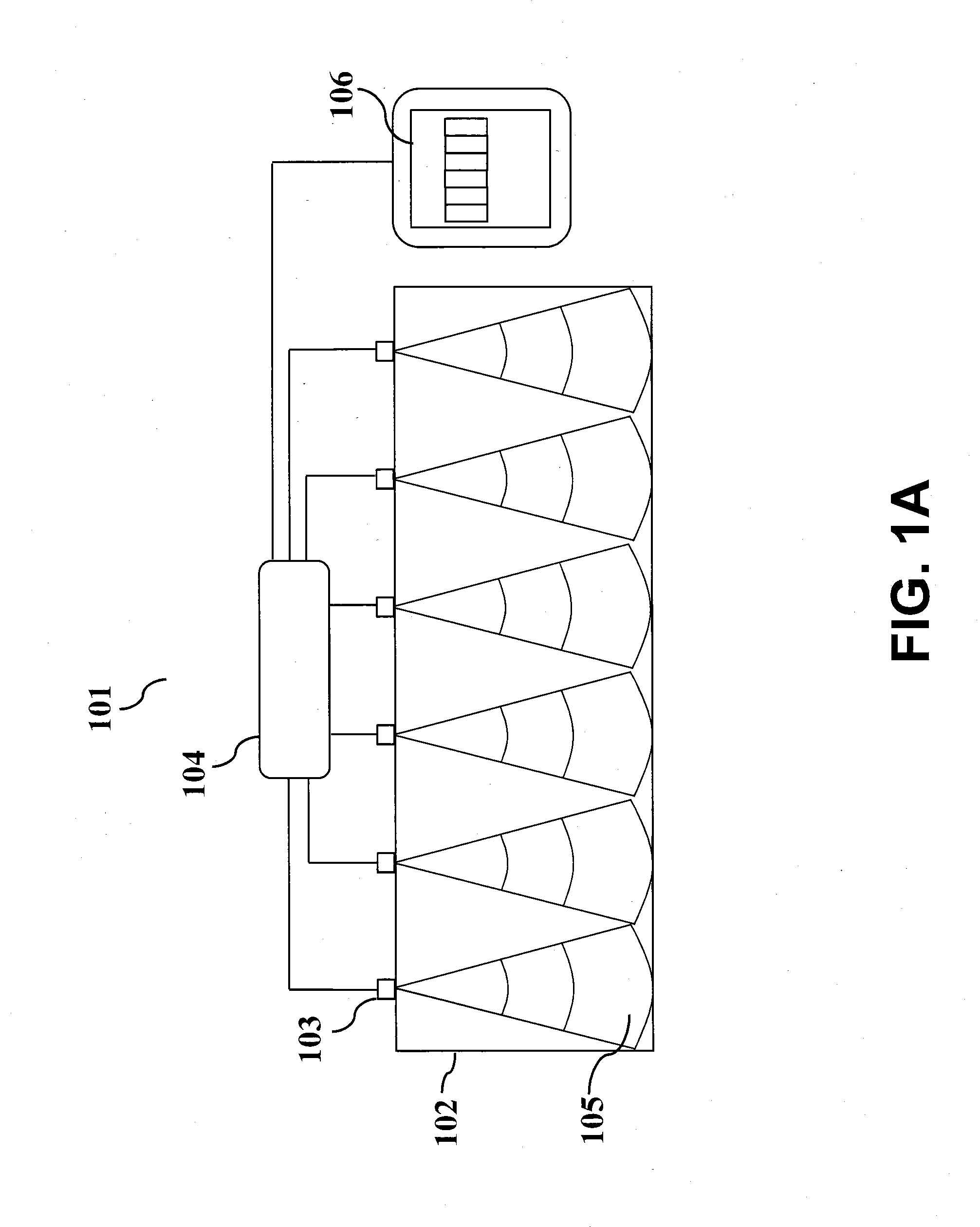
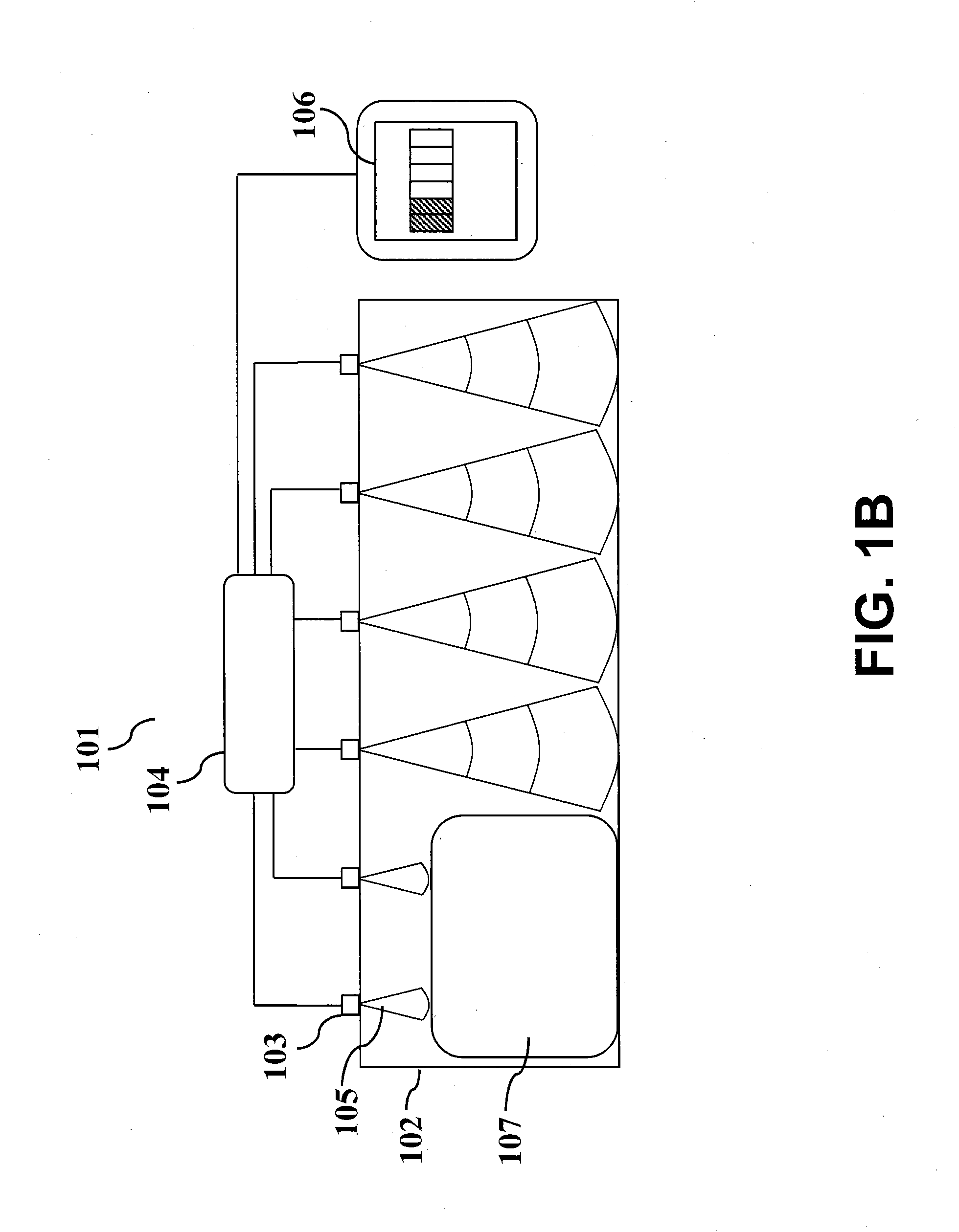
[0018]FIG. 1A is a front view illustration of a first embodiment system 101. Storage container 102 has a closeable opening (not pictured) and a monitoring system including sensors 103, which in the embodiment are ultrasonic transducers located along a line at the top of storage container 102. Sensors 103 are each configured to communicate with control circuit 104. Control circuit 104 is configured to determine the amount of space that is occupied in container 102 using input from sensors 103. In the embodiment, sensors 103 each emit an echolocation signal such as echolocation signal 105 (visualized in FIG. 1A), which will strike the nearest surface in the signal's direction of travel and produce a return signal to the emitting sensor. Preferably, the frequency of the ultrasonic waves should be such that the waves are not audible to humans. In the embodiment, at sea level and nominal temperature of 25° C., the propagation time is approximately 1100 ft / second for a 40 KHz signal. The ...
embodiment 301
[0028]FIG. 3 is an electronic schematic of embodiment 301. Control circuit 302 contains micro-controller 303, transmit multiplex 304 and receive multiplex 305. Transmit transducers 306, 307, 308, 309, 310 and 311 are each connected to transmit multiplex 304 and receive multiplex 305. Microcontroller 303 is configured to output to display 312. In the embodiment, the display is a tri-color display. In the embodiment, microcontroller 303 also receives a weight, door, temperature and altitude input.
[0029]Microcontroller 303 provides sensor selection, transmit and receive functions as well as differential calculations. In operation, microcontroller 303 selects a first transmit transducer, in this case transmit transducer 306, through transmit multiplexer 304 and sends a pulse train to transducer 306 using a transmit signal. This pulse train creates a high frequency signal. This pulse train transmits through the air in the container and is reflected by either the bottom of the container o...
PUM
 Abstract
Description
Claims
Application Information