Liquid ejecting apparatus

Active Publication Date: 2015-10-01
SEIKO EPSON CORP
View PDF4 Cites 10 Cited by
  • Summary
  • Abstract
  • Description
  • Claims
  • Application Information

AI Technical Summary

Benefits of technology

[0011]In the present invention, it is desirable if the cover is rotatably provided with regard to the opening and the cover engaging section is formed at a position that is closer to an outer edge of the cover than a center of rotation of the cover. In this manner, when the cover engaging section is provided at a position that is separated from the center of rotation, resistance from the cover engaging section when the cover moves to rotate is large compared to a case where the cover engaging section is provided at a position that is closer to the center of rotation. Accordingly, it is possible to strongly suppress positional deviation of the cover and the mounting member.
[0012]In the present invention, it is desirable if the cover engaging section is provided at two locations that are point symmetrical with the center of rotation of the cover as a reference. By doing this, the resistance is doubled since the resistance that opposes the rotation of the cover acts at both sides that interpose the center of rotation. Accordingly, it is possible to more strongly suppress positional deviation of the cover and the mounting member.
[0013]In the present invention, it is desirable if a liquid ejecting section, a connection terminal that connects with a circuit board that is provided in the liquid container, a liquid supply section that supplies liquid from the liquid container to the liquid ejecting section, and a pressurizing hole into which a pressurized fluid flows from the pressurizing section are further provided, the pressurizing hole is formed at a position that is closer to an outer edge of the cover than a center of rotation of the cover, the connection terminal and the liquid supply section are arranged at a position that is closer to the center of rotation of the cover than the pressurizing hole, and the liquid supply section is arranged at a position that is closer to the center of rotation of the cover than the connection terminal. By doing this, it is possible to arrange the liquid supply section and the connection terminal at a position where the amount of positional deviation is small in a case where the cover is rota

Problems solved by technology

There is a concern that, when the cover positionally deviates due to becoming loose, there may be defects such as ink leaking from the ink supply section, air leaking from the pressurizing

Method used


Image

  • Liquid ejecting apparatus
  • Liquid ejecting apparatus
  • Liquid ejecting apparatus

Examples


Example

[0027]An embodiment of a liquid ejecting apparatus and a liquid container which is attached to and detached from a liquid container containing section in the liquid ejecting apparatus where the present invention is applied will be described below with reference to the drawings. In the following embodiment, the present invention is applied to an ink jet printer and a liquid container which is attached to and detached from a liquid container containing section in the ink jet printer, but it is possible to apply the present invention to a liquid ejecting apparatus which ejects liquids other than ink and a liquid container in the liquid ejecting apparatus.

[0028](Overall Configuration)

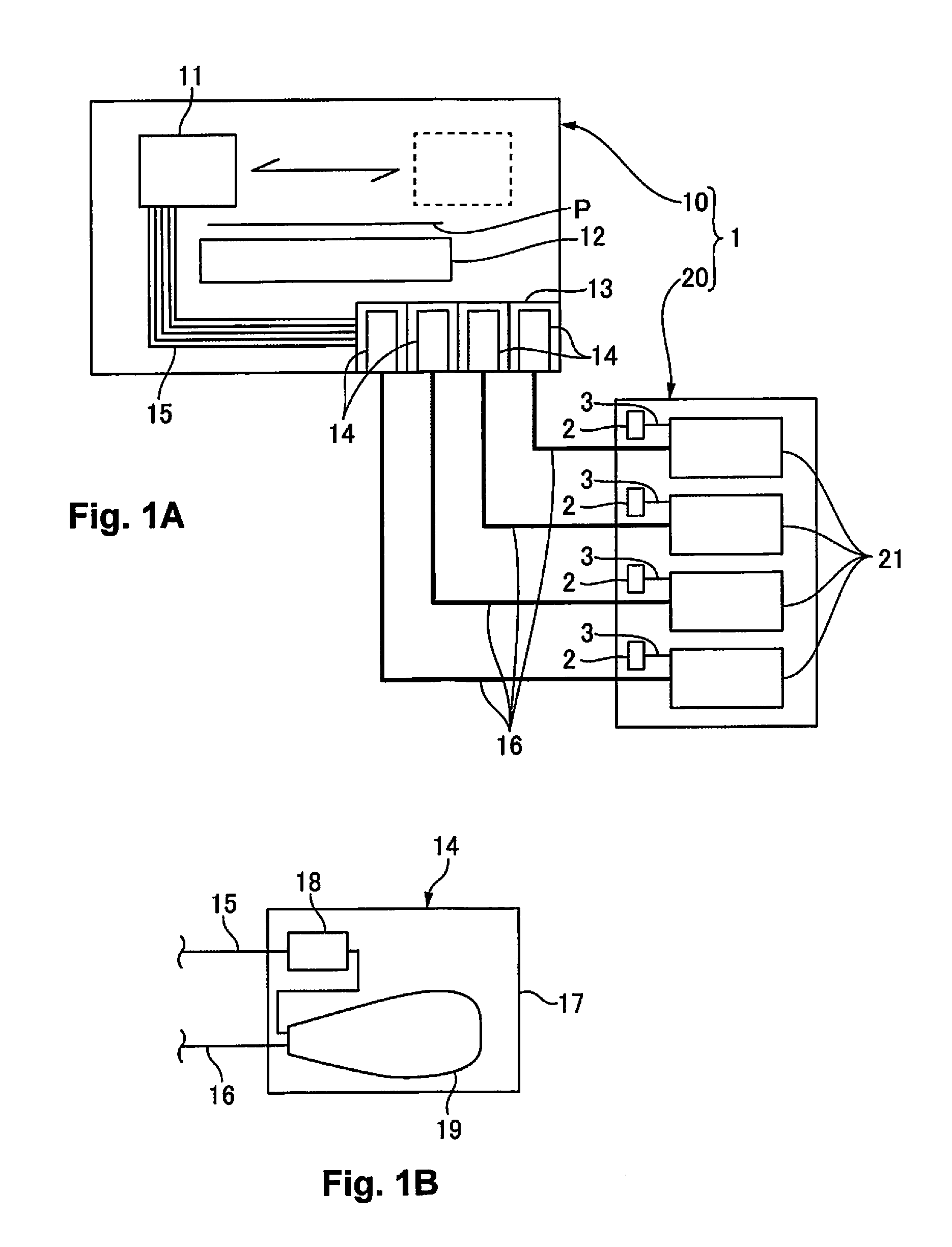
[0029]FIGS. 1A and 1B are explanatory diagrams schematically illustrating main sections of a printer where the present invention is applied, FIG. 1A illustrates the overall configuration and FIG. 1B illustrates the configuration of an intermediate tank. A printer 1 (a liquid ejecting apparatus) is an ink je...


PUM


Abstract

A liquid ejecting apparatus includes a liquid container containing section, and a pressurizing section that pressurizes inside of the liquid container containing section. The liquid container containing section has a casing that contains a liquid container, a mounting member that is mounted with the liquid container, and a cover that covers an opening that is formed in the casing, the mounting member is arranged inside the casing on the opening side, the cover is arranged outside the casing on the opening side, and the mounting member is fixed to the cover.

Description

CROSS-REFERENCE TO RELATED APPLICATIONS[0001]This application claims priority to Japanese Patent Application No. 2014-071234 filed on Mar. 31, 2014. The entire disclosure of Japanese Patent Application No. 2014-071234 is hereby incorporated herein by reference.BACKGROUND[0002]1. Technical Field[0003]The present invention generally relates to a liquid ejecting apparatus which contains a liquid container.[0004]2. Related Art[0005]In the prior art, there is a liquid ejecting apparatus which is provided with a liquid ejecting section which ejects liquid such as ink where an ink container is contained in an inner section of a pressure tank. Japanese Unexamined Patent Application Publication (Translation of PCT Application) No. 2002-512572 (PTL 1) discloses an example of this type of ink container and pressure tank. In PTL 1, a cover (a chassis 1120) is fixed to an opening in the pressure tank (a pressure container 1102). A pressurizing hole (an air inlet 1108) into which is fed pressuriz...

Claims


Application Information

Patent Timeline
IPC IPC(8): B05B9/08
CPCB05B9/0816B41J2/175B41J2/17513B41J2/1752B41J2/17523B41J2/17553B41J2/17556
Inventor NAITO, NAOKIYOSHINO, KEIICHIROFUJIMORI, RYOJIIWAMURO, TAKESHI
Owner SEIKO EPSON CORP
Why Eureka
Try Eureka