Method and lift jet floatation system for shaping thin glass

a technology of floatation system and glass, which is applied in the direction of glass reforming apparatus, glass making apparatus, glass making tools, etc., can solve the problems of glass bending between the nozzles, glass tends to distort and bend between the nozzles, and is constantly changing

Inactive Publication Date: 2015-10-01
CORNING INC
View PDF2 Cites 33 Cited by
  • Summary
  • Abstract
  • Description
  • Claims
  • Application Information

AI Technical Summary

Benefits of technology

[0007]The disclosure relates, in various embodiments, to a lift jet floatation system for shaping a glass sheet comprising a roll conveyor comprising a plurality of rollers for conveying the glass sheet along a plane, the plurality of rollers having a centerline substantially parallel to the plane; a lift jet array comprising a plurality of nozzles, one or more of the plurality of nozzles comprising a tip having a plurality of orifices; and a shaping mold, wherein the roll conveyer is positioned substantially between the lift jet array and the shaping mold, and wherein the lift jet array is positioned such that each nozzle tip is located above the centerline of the plurality of rollers.

Problems solved by technology

The production of glass panes for automobiles is a complex process, which is constantly changing due to increasingly stringent environmental and safety requirements.
However, when thinner glasses (e.g., thicknesses less than about 3.0 mm, between about 0.3 mm and about 2.0 mm, between about 0.5 mm and about 1.5 mm, and all ranges and subranges therebetween) are processed using these traditional lift jet systems, the glass tends to distort and bend between each nozzle due to the localized upward force from the nozzles.

Method used


Image

  • Method and lift jet floatation system for shaping thin glass
  • Method and lift jet floatation system for shaping thin glass
  • Method and lift jet floatation system for shaping thin glass

Examples


Embodiment Construction

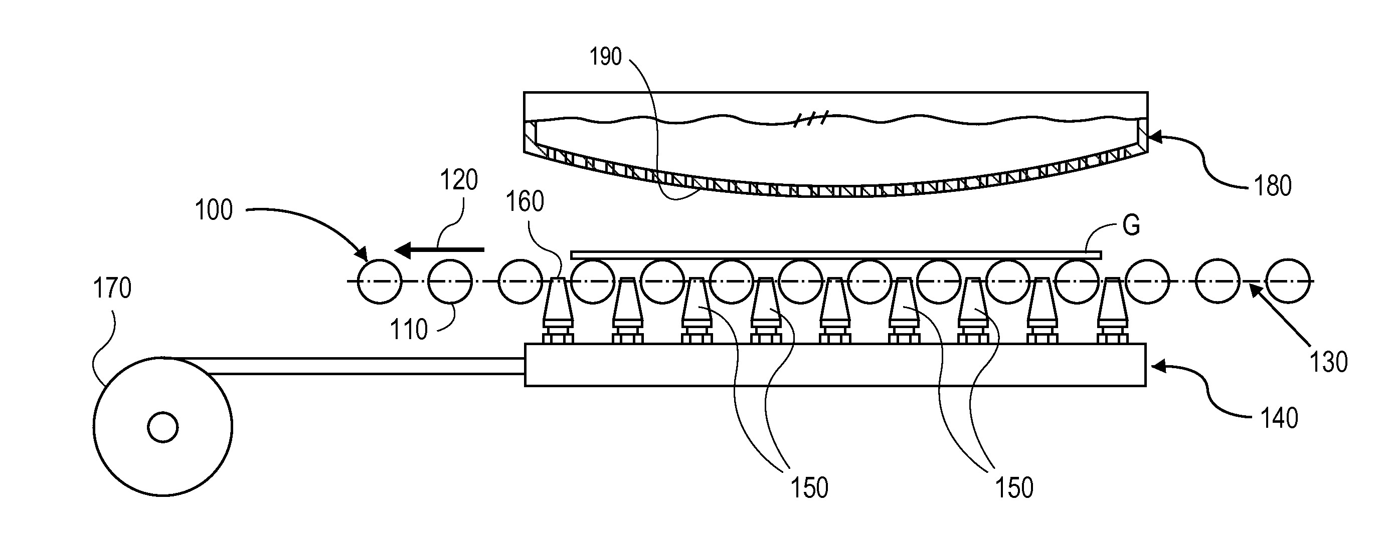
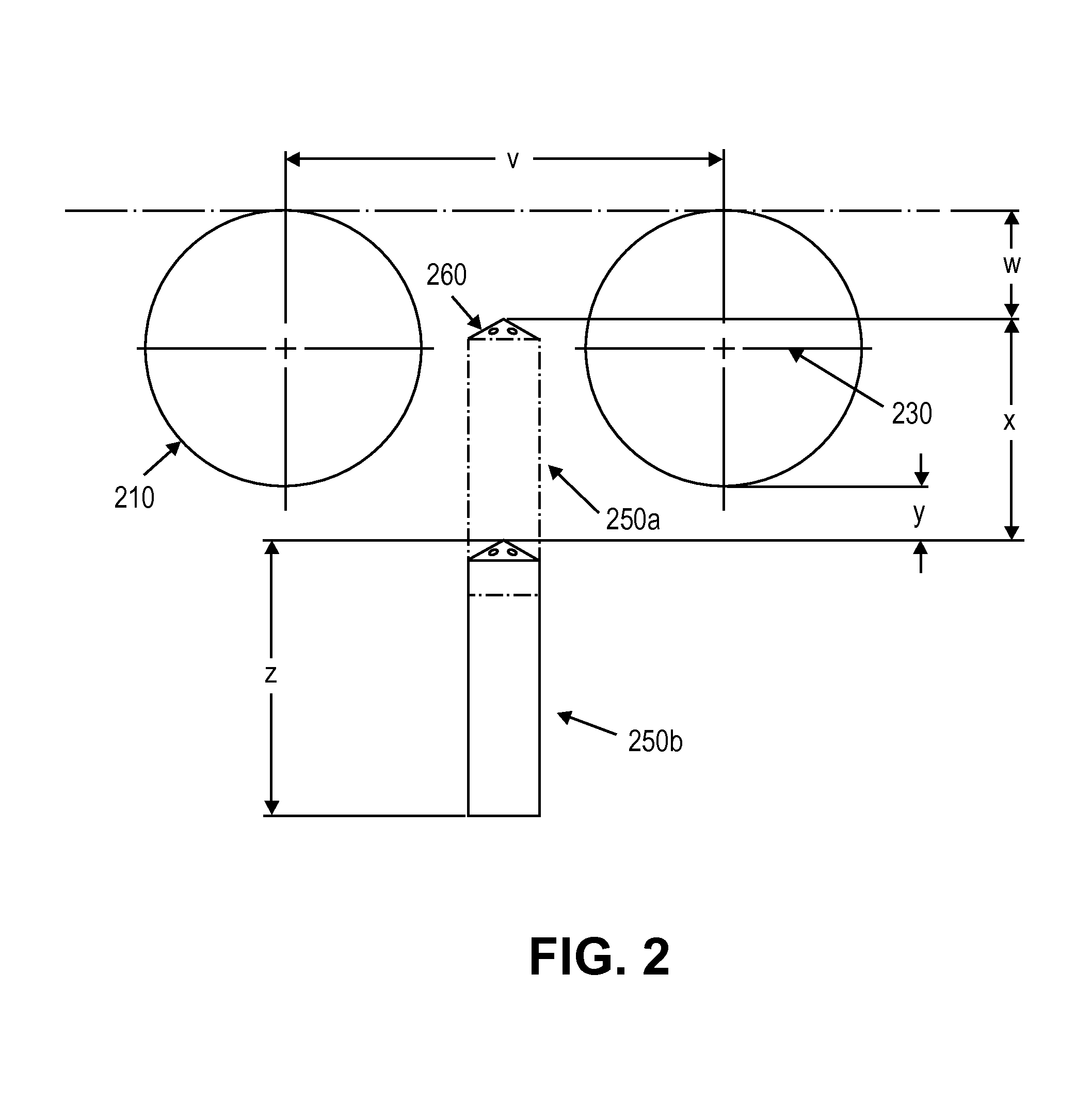
[0018]Disclosed herein is a lift jet floatation system for shaping a glass sheet comprising a roll conveyor comprising a plurality of rollers for conveying the glass sheet along a plane, the plurality of rollers having a centerline substantially parallel to the plane; a lift jet array comprising a plurality of nozzles, one or more of the plurality of nozzles comprising a tip having a plurality of orifices; and a shaping mold, wherein the roll conveyer is positioned substantially between the lift jet array and the shaping mold, and wherein the lift jet array is positioned substantially below the roll conveyor such that each nozzle tip is located above the centerline of the plurality of rollers.

[0019]Also disclosed herein is a system for lifting or shaping a glass sheet comprising a roll conveyor comprising a plurality of rollers for conveying the glass sheet along a plane, the plurality of rollers having a centerline substantially parallel to the plane, and an array of lift nozzles, ...


PUM

PropertyMeasurementUnit
temperatureaaaaaaaaaa
thicknessaaaaaaaaaa
thicknessaaaaaaaaaa

Abstract

Disclosed herein are systems for shaping a glass sheet comprising a roll conveyor comprising a plurality of rollers for conveying the glass sheet along a plane; a lift jet array comprising a plurality of nozzles, one or more of the plurality of nozzles comprising a tip having a plurality of orifices; and a shaping mold located above the roll conveyor, wherein the lift jet array is positioned below the roll conveyor such that each nozzle tip is located above the centerline of the plurality of rollers. Also disclosed herein are methods for shaping a glass sheet comprising heating the glass sheet and conveying the glass sheet on a roll conveyor to a position between the lift jet array and the shaping mold, wherein gas flows from the lift jet array with a force sufficient to lift the glass sheet from the roll conveyor.

Description

CROSS-REFERENCE TO RELATED APPLICATIONS[0001]This application claims the benefit of priority under 35 U.S.C. §119 of U.S. Provisional Application Ser. No. 61 / 972,784 filed on Mar. 31, 2014 the content of which is relied upon and incorporated herein by reference in its entirety.FIELD OF THE DISCLOSURE[0002]The disclosure relates generally to methods and systems for shaping glass sheets, and more particularly to lift jet floatation systems for bending thin glasses.BACKGROUND[0003]The ability to thermally shape and form thin glass sheets is increasingly relevant to various industries, such as the automotive industry. The production of glass panes for automobiles is a complex process, which is constantly changing due to increasingly stringent environmental and safety requirements. The demand for intricate glass shapes with high optical quality and low weight is growing as governmental regulations require increased fuel economy and reduced emissions. The ability to make automotive parts ...

Claims


Application Information

Patent Timeline
Patent Type & Authority Applications(United States)
IPC IPC(8): C03B23/03C03B35/16
CPCC03B35/16C03B23/03C03B23/035C03B23/0357C03B35/18C03B35/24Y02P40/57
Inventor BRENNAN, MICHAEL TIMOTHYJAIN, ANURAGLOCK, WILLIAM EDWARDMOORE, MICHAEL JOHNSMITH, LARRY GENEWASSON, KEVIN LEE
Owner CORNING INC
Why Eureka
Try Eureka