Effort-Saving Locking Pliers

a technology of locking pliers and clamping objects, which is applied in the field of can solve the problem that the pair of locking pliers is still required a great amount of effort to release from the clamped obj

Active Publication Date: 2015-10-08
WU MING CHIEH
View PDF4 Cites 14 Cited by
  • Summary
  • Abstract
  • Description
  • Claims
  • Application Information

AI Technical Summary

Problems solved by technology

However, a great effort is still needed to release the pair of locking pliers from the clamped object.

Method used


Image

  • Effort-Saving Locking Pliers
  • Effort-Saving Locking Pliers
  • Effort-Saving Locking Pliers

Examples


Embodiment Construction

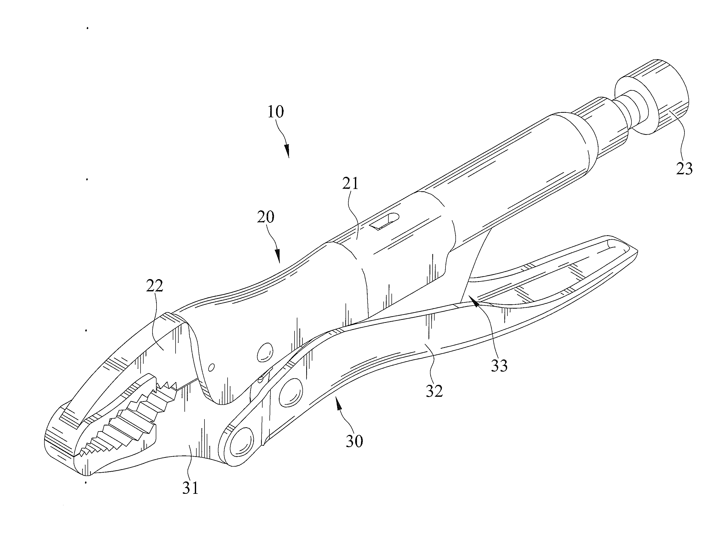
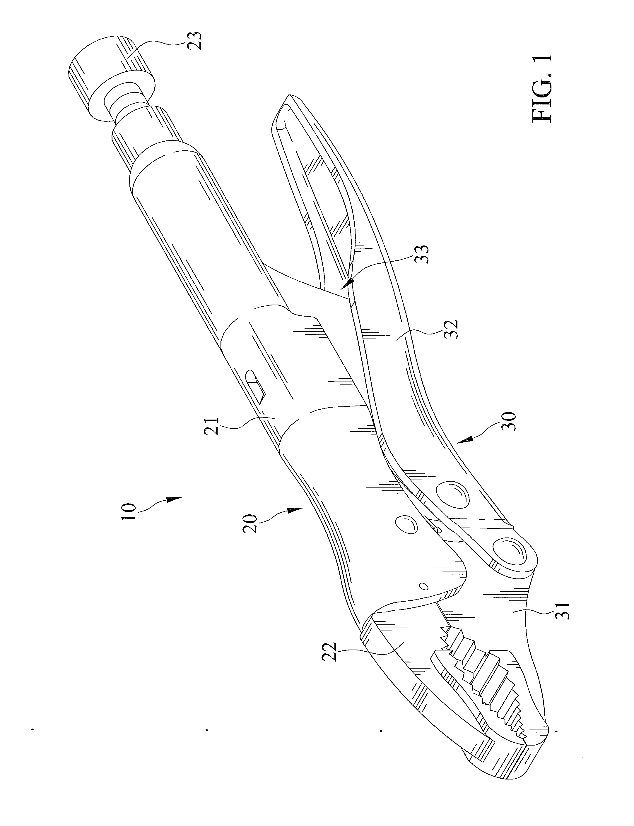
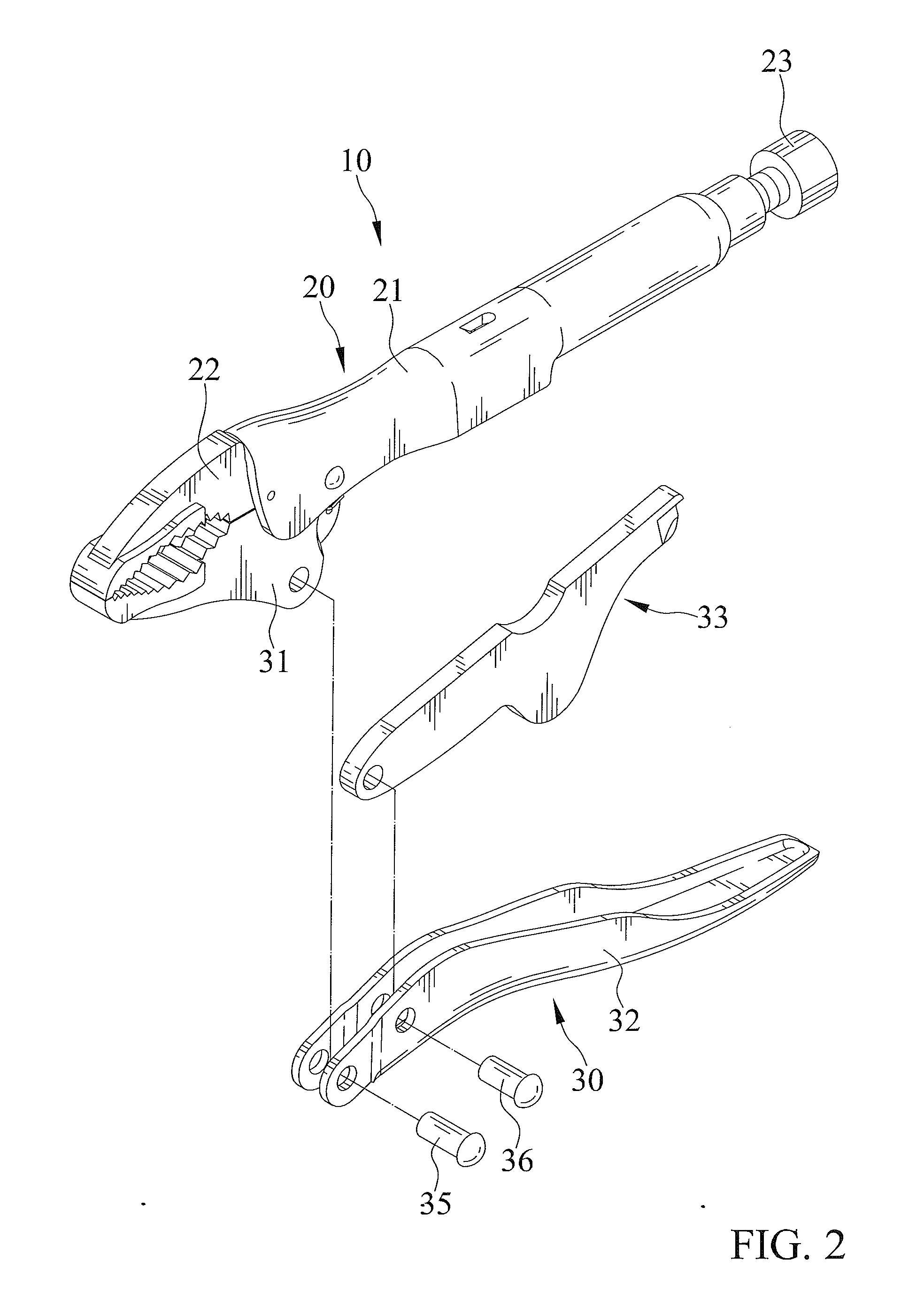
[0019]FIGS. 1 through 3 show a pair of locking pliers 10 according to a first embodiment of the present invention. The pair of locking pliers 10 includes a first grip structure 20, a second grip structure 30, a lock mechanism 33, and a basing member 34.

[0020]The first grip structure 20 includes a first handle 21, a first jaw 22 connected to and fixedly disposed on the first handle 21, and an adjustment screw 23 connected to the first handle 21 and being movable to various fixed positions on the first handle 21. The first handle 21 has two opposite ends. The first jaw 22 and the adjustment screw 23 are at opposite ends of the first handle 21. The first handle 21 extends in a lengthwise direction form a first end to a second end thereof The first jaw 22 extends in a lengthwise direction from a first end to a second thereof The first handle 21 includes the first end thereof connected to the second end of the first jaw 22. The first end of the first jaw 22 is at a first distal end of th...


PUM


Abstract

A pair of locking pliers includes a first grip structure including a first jaw and an adjustment screw connected to a first handle. A second grip structure cooperates with the first grip structure. The second grip includes a second jaw pivotally connected to the first handle about a first pivot axis and a second handle pivotally connected to the second jaw about a second pivot axis. A lock mechanism is pivotally connected to the second handle about a third pivot axis. The lock mechanism abuts the adjustment screw which restrains the lock mechanism to the first handle. The second handle extends longitudinally and terminates at an end at a first length from the second pivot axis. A second length measures a distance between the first and second pivot axes. The second length is smaller than 0.19 times of the first length.

Description

CROSS REFERENCE TO RELATED APPLICATION[0001]The present application is a continuation-in-part application of U.S. patent application Ser. No. 14 / 485,884 filed on Sep. 15, 2014, of which the disclosure is incorporated herein.BACKGROUND OF THE INVENTION[0002]1. Field of the Invention[0003]This invention relates to a pair of locking pliers and, more particularly to a pair of effort-saving locking pliers.[0004]2. Description of the Related Art[0005]TW Pat. No. 1411498 shows a pair of locking pliers including two jaws, two handles connected respectively to the two jaws, and a locking mechanism connected between the two handles. The handles can be squeezed to close the jaws. The pair of locking pliers can be locked to an object, with the locking mechanism causing the jaws clamped to the object. However, a great effort is still needed to release the pair of locking pliers from the clamped object.[0006]The present invention is, therefore, intended to obviate or at least alleviate the proble...

Claims


Application Information

Patent Timeline
Patent Type & Authority Applications(United States)
IPC IPC(8): B25B7/12
CPCB25B7/123
Inventor WU, MING CHIEH
Owner WU MING CHIEH
Why Eureka
Try Eureka