Flexible tilt adjustment device for a chair back

a flexible, back tilt technology, applied in the field of chairs, can solve the problems of inability to adjust the whole adjustment structure, inconvenience in operation, and spring elastic fatigue, and achieve the effect of adjusting the back tilt without effor

Active Publication Date: 2015-10-15
DONGGUAN KENTEC OFFICE SEATING
View PDF8 Cites 11 Cited by
  • Summary
  • Abstract
  • Description
  • Claims
  • Application Information

AI Technical Summary

Benefits of technology

[0007]An object of the invention is to provide a flexible back t

Problems solved by technology

However, this spring tends to elastic fatigue.
This causes inconvenience in operation.
When the link set 65 has jammed, the whole adjustment structure cannot work.
Fu

Method used


Image

  • Flexible tilt adjustment device for a chair back
  • Flexible tilt adjustment device for a chair back
  • Flexible tilt adjustment device for a chair back

Examples


Embodiment Construction

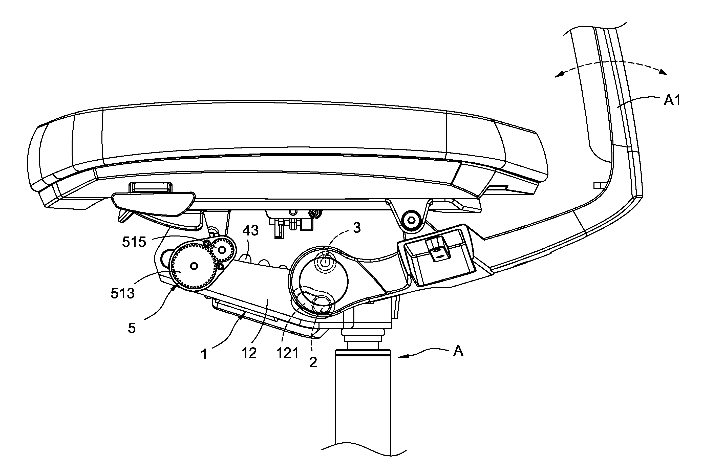
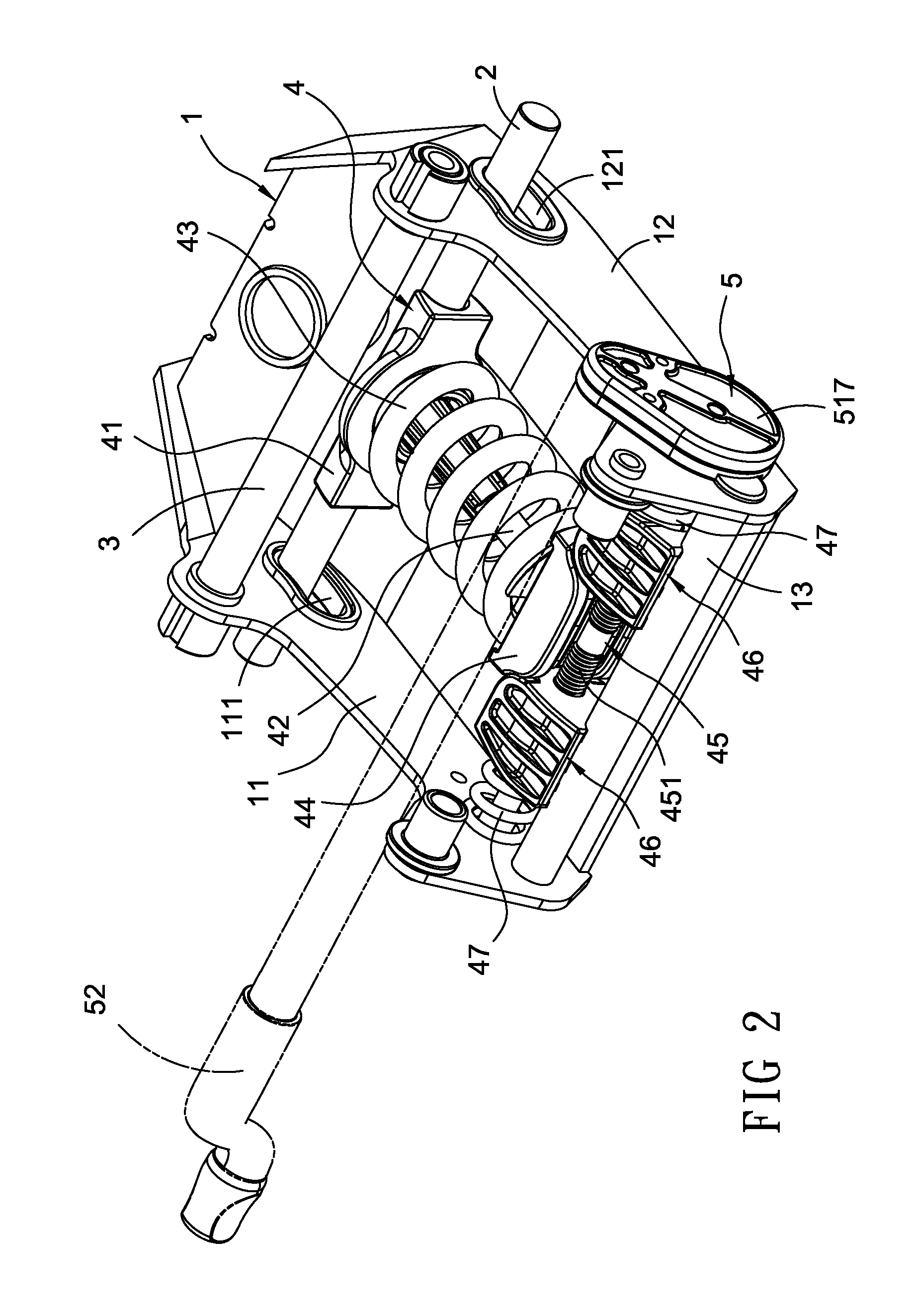
[0016]Please refer to FIGS. 2-4. The flexible adjustment device of the invention includes a hollow seat 1. Two sides of the seat 1 are formed with two parallel and symmetric edge plates 11, 12. The two edge plates 11, 12 are separately provided with two long holes 111, 121. In this embodiment, these long holes 111, 121 are arc-shaped. The two edge plates 11, 12 are separately provided with two through holes 112, 122 and two fixing holes 113, 123. A fixing rod 13 passes through the fixing holes 113, 123. One end of the fixing rod 13 is provided with a plug 131 for allowing to remove the fixing rod 13.

[0017]The long holes 111, 121 of the seat 1 is passed through by a first rod 2 connected to a chair back. A length of the long holes 111, 121 is greater than a diameter of the first rod 2 to make the first rod 2 movable therein. A second rod 3 passes through the seat 1 near the first rod 2. In this embodiment, the second rod 3 is placed above the first rod 2. The second rod 3 is used for...


PUM


Abstract

The adjustment device includes a seat connected to a back by a first rod and an elasticity set. The elasticity has a base connected to the first rod. A pressing rod is connected to the base. A first spring is passed through by the pressing rod and stopped by the base. A pushing block is connected to the pressing rod and the first spring. A rotating rod passes through the seat. Two pressing blocks with a threaded hole are passed by the rotating rod and separately screwed with the rotating rod. Two second springs are passed through by the rotating rod and nipped between the pressing blocks and the edge plates.

Description

BACKGROUND OF THE INVENTION[0001]1. Technical Field[0002]The invention relates to chairs, particularly to back tilt adjustment of chairs.[0003]2. Related Art[0004]Some office chairs are provided with a back tilt adjustment function. Such a function is typically accomplished by a spring between a cushion and a back. However, this spring tends to elastic fatigue.[0005]Some chairs adopt a flexible tilt adjustment structure as shown in FIG. 1. The structure is fixed to a seat 61 through an adjustment rod 60. An end of the adjustment rod 60 connects a driving block 62. The seat 61 is provided with a transmission rod 63. The transmission rod 63 is pivotally connected to the driving block 62. A spring 64 is passed by the transmission rod 63. The seat 61 is provided with a sway element 66 connected to a back. The sway element 66 is pushed by the spring 64. Thus the back can be adjusted by moving the transmission rod 63 flexibly pushed by the spring 64.[0006]In above structure, rotating the ...

Claims


Application Information

Patent Timeline
IPC IPC(8): A47C7/44
CPCA47C7/443A47C7/441A47C1/03266A47C1/03272
Inventor SU, CHIH-CHENG
Owner DONGGUAN KENTEC OFFICE SEATING
Why Eureka
Try Eureka