Vehicle lighting apparatus with multizone proximity control

a technology of proximity control and vehicle lighting, applied in the direction of vehicle spotlighting, interior lighting, transportation and packaging, etc., can solve the problems of vehicle occupants being distracted, vehicle occupants being relying on the vehicle occupants,

a technology of proximity control and vehicle lighting, applied in the direction of vehicle spotlighting, interior lighting, transportation and packaging, etc., can solve the problems of vehicle occupants being distracted, vehicle occupants being relying on the vehicle occupants,

US20150298607A1Active Publication Date: 2015-10-22FORD GLOBAL TECH LLC

Image

  • Vehicle lighting apparatus with multizone proximity control
  • Vehicle lighting apparatus with multizone proximity control
  • Vehicle lighting apparatus with multizone proximity control

Examples


Embodiment Construction

[0020]As required, detailed embodiments of the present disclosure are disclosed herein. However, it is to be understood that the disclosed embodiments are merely exemplary of the disclosure that may be embodied in various and alternative forms. The figures are not necessarily to a detailed design and some schematics may be exaggerated or minimized to show function overview. Therefore, specific structural and functional details disclosed herein are not to be interpreted as limiting, but merely as a representative basis for teaching one skilled in the art to variously employ the present disclosure.

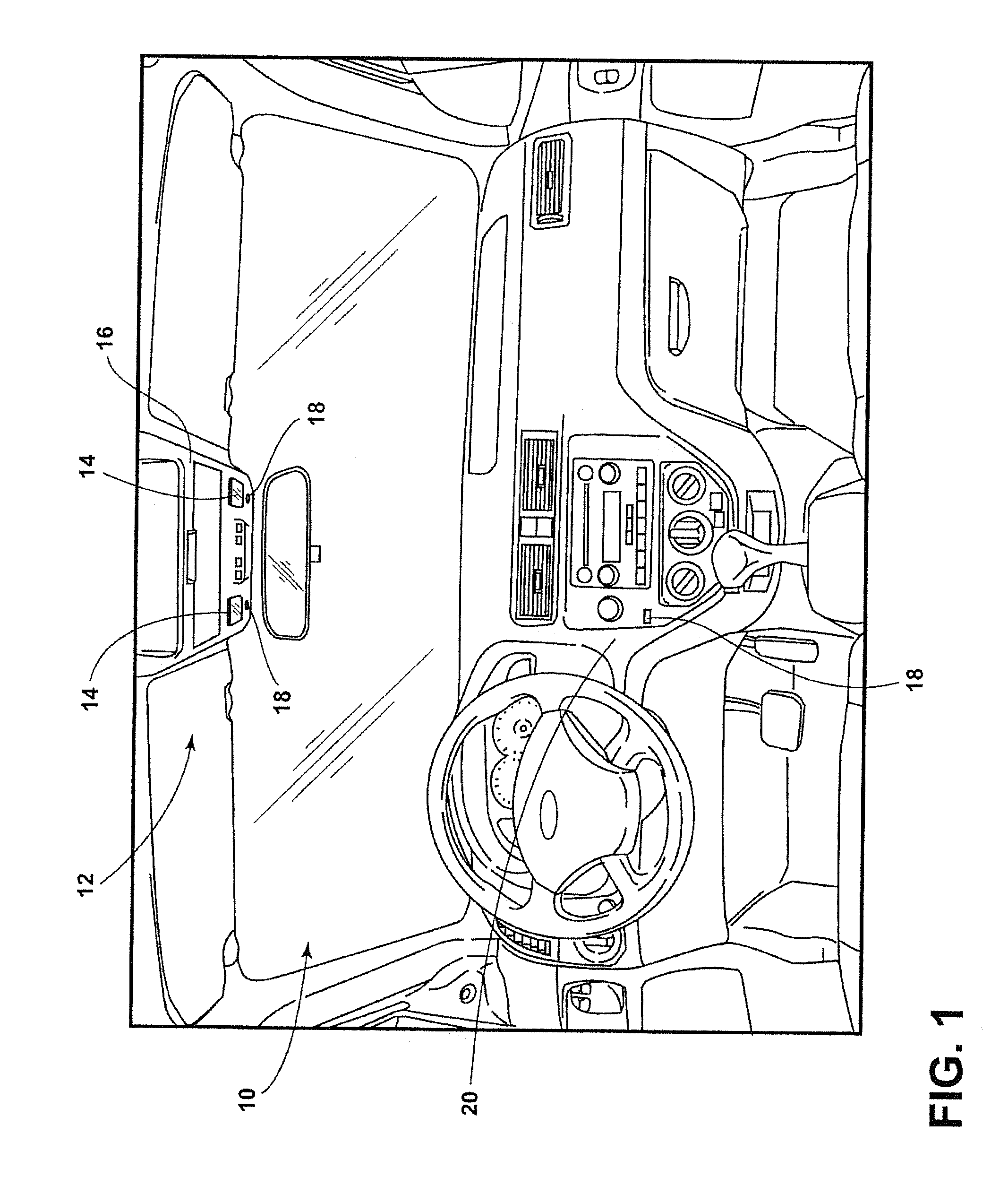
[0021]Referring to FIG. 1, the front vehicle passenger compartment 10 of a wheeled vehicle 12 is generally illustrated having at least one reading lamp 14 assembled in an overhead console 16. In the illustrated embodiment, the overhead console 16 is assembled to the interior side of the headliner of the front vehicle passenger compartment 10 and positioned in a central location in the front ...


PUM


Abstract

A vehicle lighting system is disclosed. The lighting system comprises a group of light sources having a plurality of portions. Each of the portions has a proximity sensor configured to communicate a signal to control a portion of the plurality of portions. A controller is in communication with the light sources and the proximity sensors. The controller is operable to selectively activate a first portion of the grouping of light sources in response to a first proximity detection, and activate the plurality of portions in response to a second proximity detection.

Description

CROSS-REFERENCE TO RELATED APPLICATION[0001]This patent application is a continuation-in-part of U.S. patent application Ser. No. 14 / 257,309, filed Apr. 21, 2014, and entitled “VEHICLE READING LAMP WITH LOW INTENSITY LIGHT SETTING,” the entire disclosure of which is incorporated herein by reference.FIELD OF THE INVENTION[0002]The present disclosure generally relates to vehicle lighting, and more particularly to directional interior vehicle lighting.BACKGROUND OF THE INVENTION[0003]Currently, some lighting devices require a user to interact with an outer lens in order to activate and deactivate the lighting devices. One downside to such a design is that a vehicle occupant typically has to rely on tactile sensations to locate the outer lens when dark conditions are present. As a result, some vehicle occupants may become distracted with having to feel for the position of the outer lens when desiring to activate the lighting devices. Therefore, there is a need for a lighting device that...

Claims


Application Information

Patent Timeline
22 Oct 2015
Publication
US20150298607A1
IPC
B60Q3/02
CPC
B60Q3/0286; B60Q3/0293; B60Q3/82; B60Q3/64; B60Q3/76; B60Q3/80
Inventors
SALTER, STUART C.; DUNHAM, SCOTT HOLMES