Solar photovoltaic panel and solar photovoltaic system

a solar photovoltaic and solar panel technology, applied in diversity/multi-antenna systems, power supply testing, pv power plants, etc., can solve problems such as difficult examination tasks, and achieve the effects of improving traceability on the distribution channel, easy collection of information, and easy retrieval

Inactive Publication Date: 2015-11-05
MITSUBISHI ELECTRIC CORP
View PDF5 Cites 64 Cited by
  • Summary
  • Abstract
  • Description
  • Claims
  • Application Information

AI Technical Summary

Benefits of technology

[0008]The solar photovoltaic panel having the above-described configuration makes it possible to easily collect information of an individual panel, physical panel placement information, and wiring construction information such as series connection order of solar photovoltaic panels after the construction. Furthermore, the system configured to additionally have means for measuring the power generation states of individual panels so as to acquire the information via a short distance communication coil and wireless-transfer the information makes it possible

Problems solved by technology

However, the examinat

Method used


Image

  • Solar photovoltaic panel and solar photovoltaic system
  • Solar photovoltaic panel and solar photovoltaic system
  • Solar photovoltaic panel and solar photovoltaic system

Examples


embodiment 1

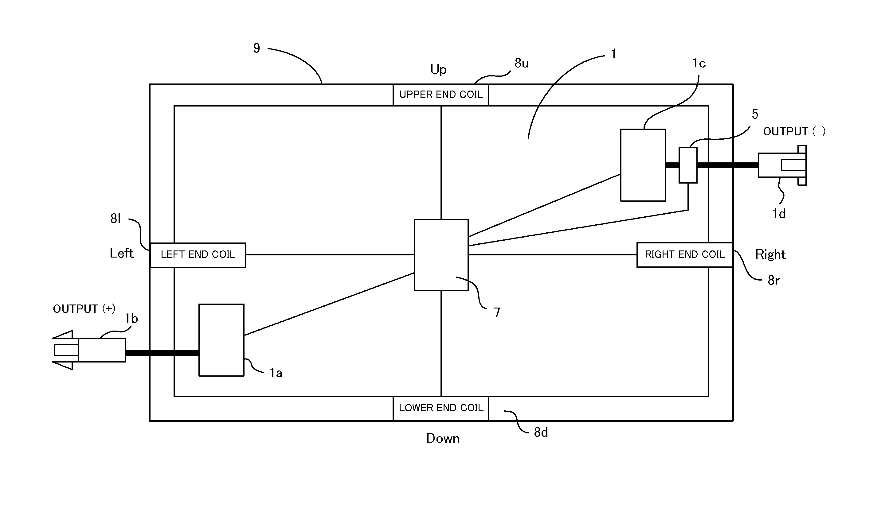
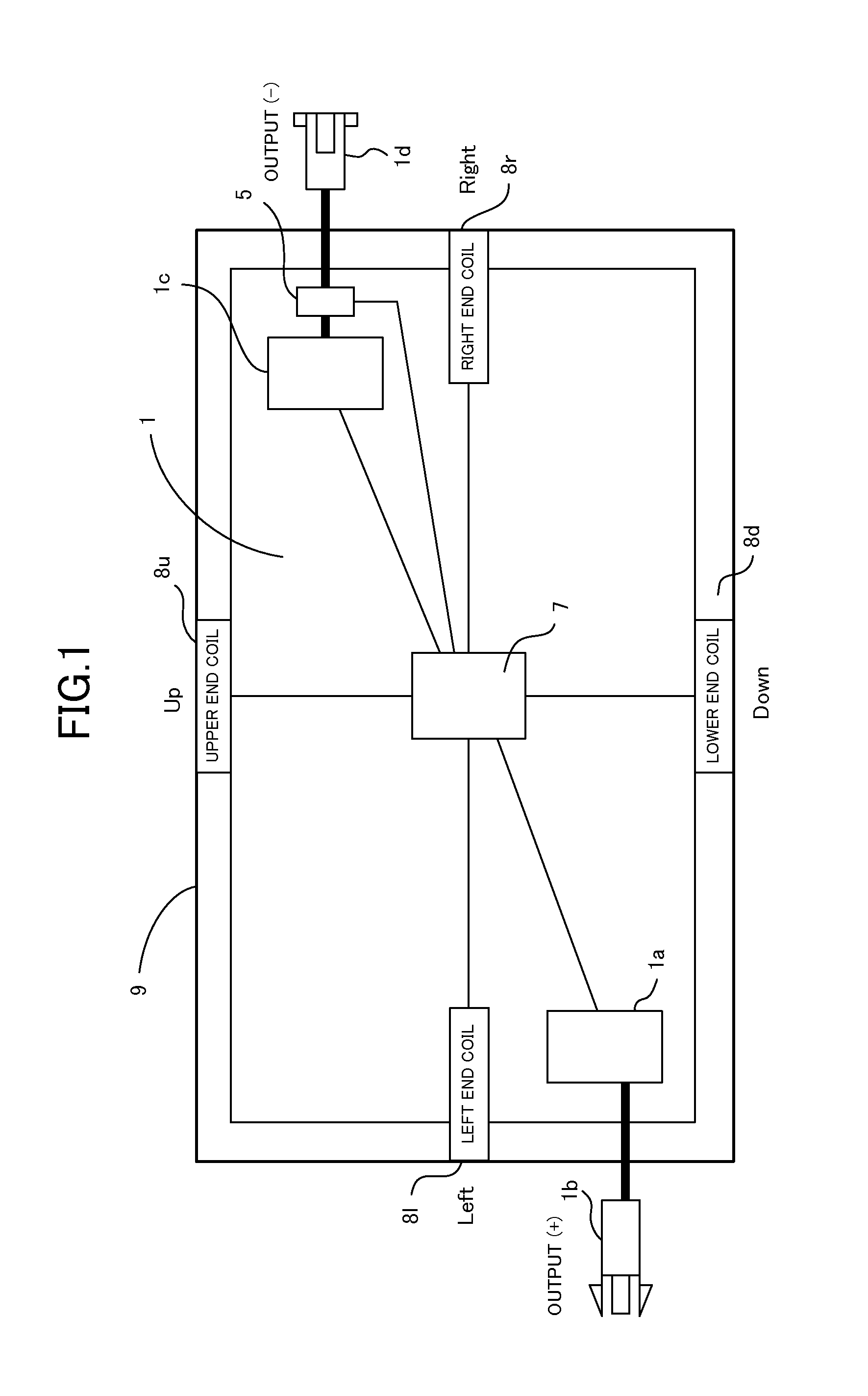
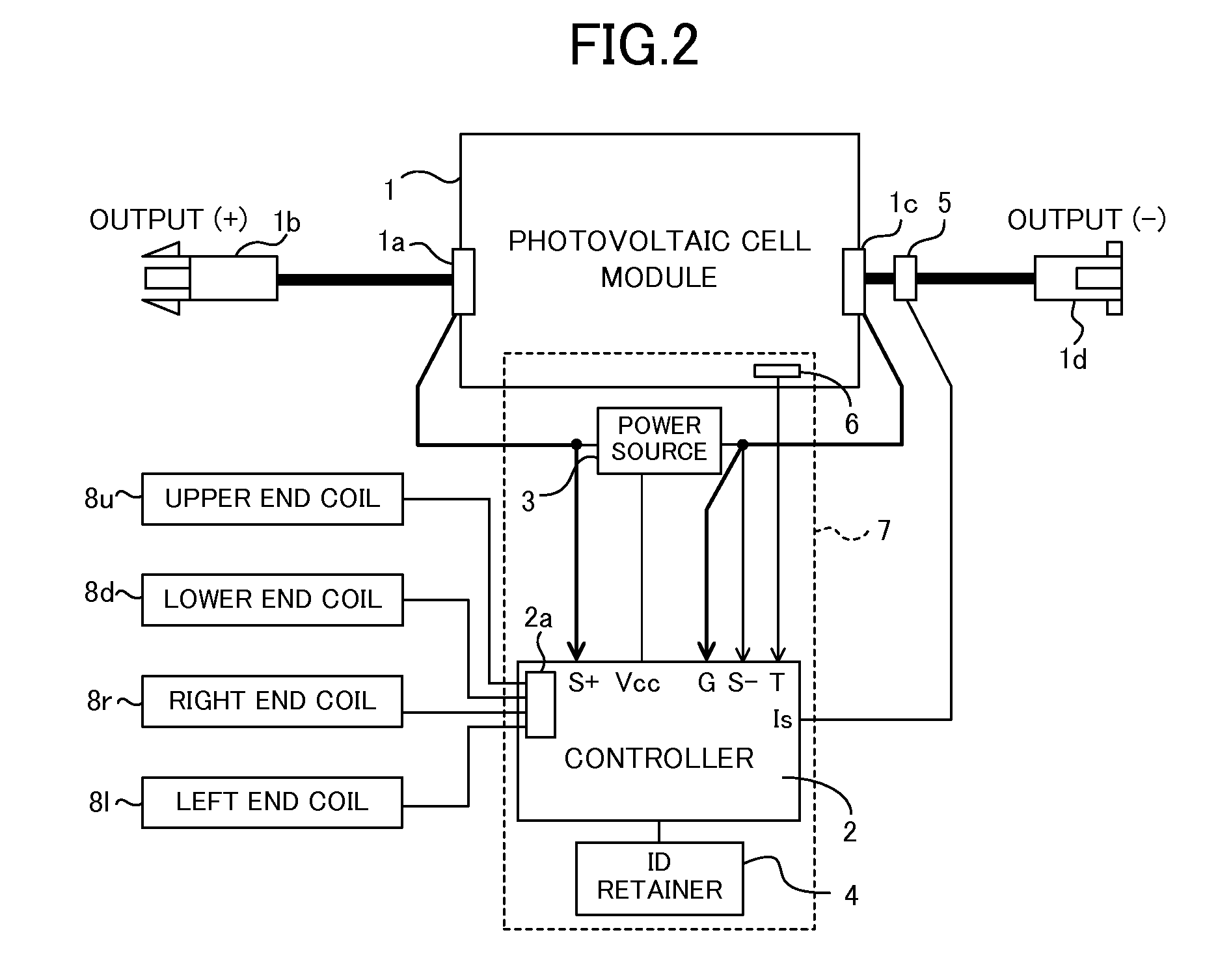
[0033]The solar photovoltaic panel 9 (9A to 9F) according to the embodiment is arrayed in a matrix for use as shown in FIG. 3. Each solar photovoltaic panel 9 comprises, as shown in FIG. 1, a photovoltaic cell module 1, a + (positive) terminal box 1a, a + (positive) output connector 1b, a − (negative) terminal box 1c, a − (negative) output connector 1d, a current sensor 5, a housing box 7, an upper end coil 8u, a lower end coil 8d, a right end coil 8r, and a left end coil 8l.

[0034]The photovoltaic cell module 1 comprises, for example, photovoltaic cells using silicon crystal, which is considered to contribute to highly efficient energy conversion, converting the light energy of sunlight and the like to electric power and outputting the electric power. The silicon-based photovoltaic cell includes those of crystalline silicon, polycrystal silicon, and amorphous silicon types.

[0035]The + terminal box 1a and − terminal box 1c are connected to the + output terminal and − output terminal...

modified embodiment 1

[0120]In the above embodiment, information regarding a search rejection signal is not transferred to the measuring device 10. However, like a response signal, it is possible to transfer a search rejection signal to the measuring device 10 with the addition of information indicating the transfer path. As a result, it is possible to acquire not only the placement information of solar photovoltaic panels 9 but also information indicating the facing relationship between the coils 8.

embodiment 2

[0121]In the above embodiment, a case in which the placement information indicating the physical placement of solar photovoltaic panels 9 is described. The present disclosure is not restricted thereto. The present disclosure is applicable to examination of the connection relationship (wiring path) of solar photovoltaic panels 9.

[0122]An embodiment of examining the connection relationship of solar photovoltaic panels 9 is described hereafter.

[0123]In this embodiment, as shown in FIGS. 8 and 9, the + output connector 1b and − output connector 1d of a solar photovoltaic panel 9 have a coil 8p and a coil 8m, respectively. As the + output connector 1b (or − output connector 1d) of an adjoining solar photovoltaic panel 9 and the − output connector 1d (or + output connector 1b) of an adjoining solar photovoltaic panel 9 are connected, the adjoining solar photovoltaic panels 9 are series-connected. Then, of the adjoining solar photovoltaic panels 9, the coil 8p provided at the + output conn...


PUM


Abstract

A solar photovoltaic panel disposed in a matrix for use, wherein the solar photovoltaic panel comprises a plurality of antennas configured to communicate with antennas placed on adjoining solar photovoltaic panels, a receptor configured to receive a search command via the plurality of antennas, a transmitter configured to transmit a search command from the antennas excluding the antenna having received the search command in response to the received search command, and a responder configured to create a response signal including the panel ID of its own solar photovoltaic panel and transmit the response signal from the antenna having received the search command when no response signal to the search command transmitted from the transmitter is received, and when a response signal to the search command transmitted from the transmitter is received, transmit the response signal with the addition of information from the antenna having received the search command.

Description

TECHNICAL FIELD[0001]The present disclosure relates to a solar photovoltaic panel and solar photovoltaic system.BACKGROUND ART[0002]In construction of a solar photovoltaic system, some variance may occur between the designed (planned) construction and the actual construction. Therefore, after the construction, the wiring and placement of solar photovoltaic panels are examined to obtain wiring path information and placement information. However, the examination task is not easy.[0003]Non Patent Literature 1 discloses a technique of facilitating the above examination task. The technique investigates the wiring paths and placement by applying high frequency signals to the wiring paths and examining the paths where the signals are detected.CITATION LISTNon Patent Literature[0004]Non Patent Literature 1: Solar Photovoltaic System Failure Case File, p 74, Nikkan Kogyo Shimbun Ltd. (Business & Technology Daily News).SUMMARY OF INVENTIONTechnical Problem[0005]The technique disclosed in the ...

Claims


Application Information

Patent Timeline
IPC IPC(8): H01L31/02H02S40/32H04B7/04G01R31/40
CPCH01L31/02021H04B7/04H02S40/32H02S50/00
Inventor HIGUMA, TOSHIYASU
Owner MITSUBISHI ELECTRIC CORP
Why Eureka
Try Eureka