Vehicle airbag device

a technology for airbags and vehicles, applied in the direction of vehicular safety arrangments, pedestrian/occupant safety arrangements, vehicular components, etc., can solve the problems of interior component breakage, interior component obstructing inflation, inflation and deployment characteristics of the second bag suffer, etc., to improve the restraint performance of the occupant, suppress or prevent the effect of an interior component from obstructing inflation

Active Publication Date: 2015-12-24
TOYOTA JIDOSHA KK
View PDF3 Cites 57 Cited by
  • Summary
  • Abstract
  • Description
  • Claims
  • Application Information

AI Technical Summary

Benefits of technology

[0010]In the vehicle airbag device of the present aspect, the airbag is provided at the back side of the instrument panel, and the airbag receives a supply of gas from the inflator and inflates and deploys toward the front side of the instrument panel. Specifically, the first bag of the airbag inflates and deploys at the vehicle front side of an occupant, and the second bag of the airbag inflates and deploys at the vehicle width direction center side of the first bag. The occupant attempting to move obliquely toward the front and the vehicle width direction center side during an oblique collision of the vehicle is accordingly restrained by the second bag. This thereby enables restraint performance of the occupant to be improved.
[0011]Note that the recess open toward the vehicle lower side is formed at the lower face of the second bag when inflated and deployed, and the recess covers the interior component installed at the vehicle width direction central portion of the instrument panel from the vehicle upper side. Namely, the airbag inflates and deploys such that the recess of the second bag covers the interior component from the vehicle upper side. This thereby enables the interior component to be suppressed or prevented from obstructing inflation and deployment of the second bag. The second bag may also be configured so as to enfold the interior component in the vehicle front-rear direction following inflation and deployment of the second bag. This thereby enables a front end portion of the second bag to be supported by the interior component, and enables a reaction force from the second bag to be act on the occupant during an oblique collision of the vehicle.
[0012]Due to the above, the vehicle airbag device of the present aspect is capable of improving restraint performance of an occupant, while suppressing or preventing an interior component from obstructing inflation and deployment of a second bag disposed on a vehicle width direction center side.

Problems solved by technology

However, when, for example, an interior component such as a display is installed at a vehicle width direction central portion of an instrument panel, there is a possibility of the interior component obstructing inflation and deployment of a second bag, such that the inflation and deployment characteristics of the second bag suffer.
When this occurs, there is also a concern of breakage of the interior component.
In a case in which a leading end portion of the second bag is configured in a shape to avoid the interior component, support from the second bag with respect to load from the vehicle rear side becomes insufficient, and a sufficient reaction force may not act on the occupant from the second bag in an oblique collision of the vehicle.

Method used


Image

  • Vehicle airbag device
  • Vehicle airbag device
  • Vehicle airbag device

Examples


modified examples

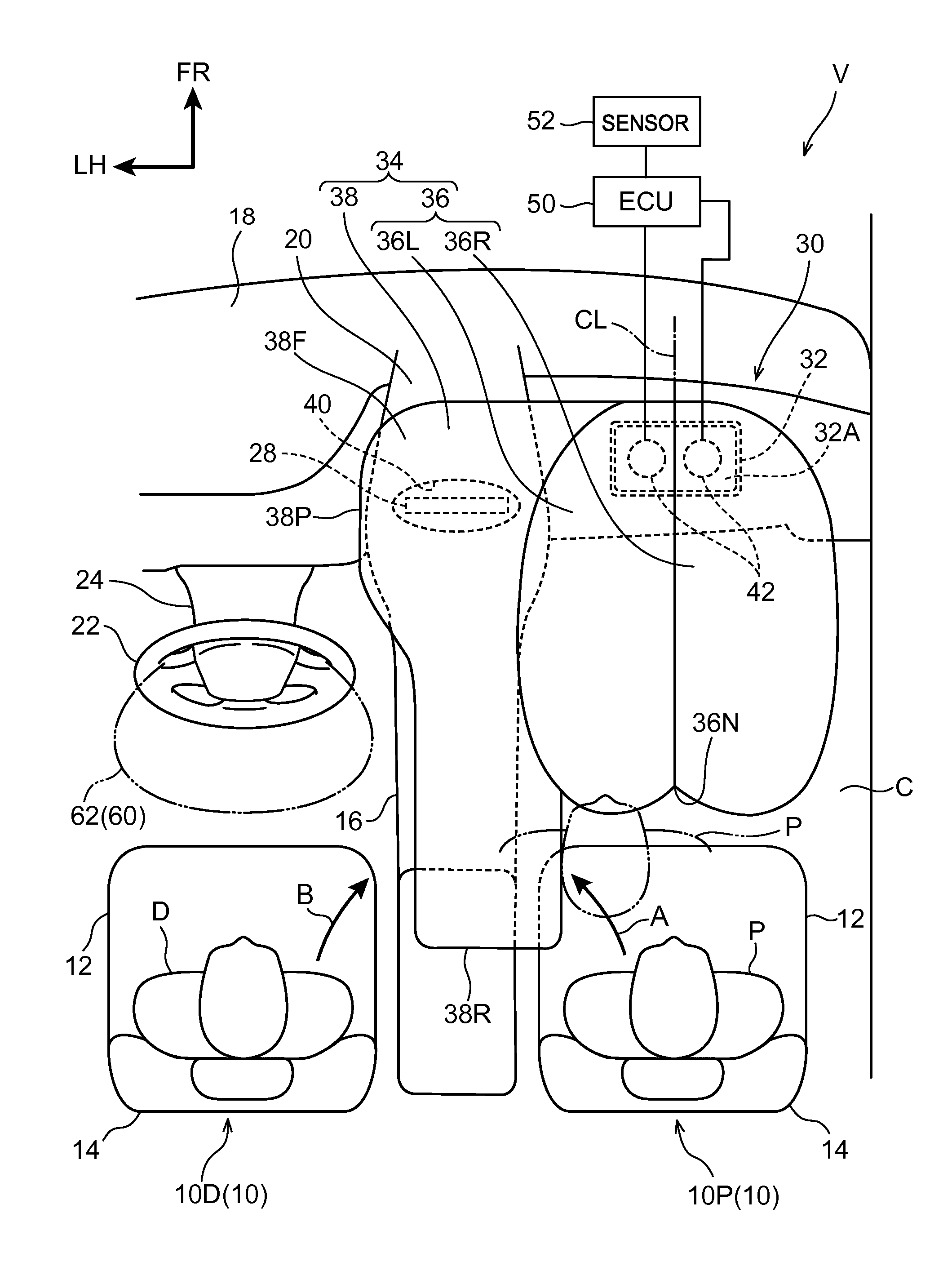
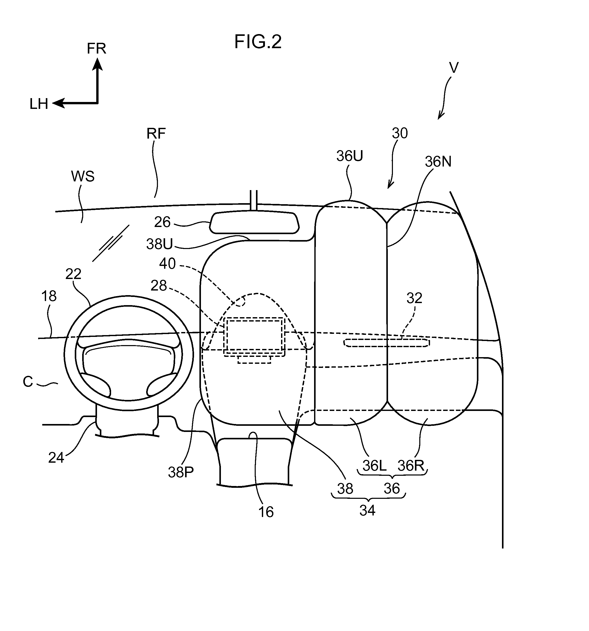
[0046]In the present exemplary embodiment, the recess 40 formed at the lower face of the center airbag 38 is formed in a substantially elliptical cone shape opening toward the lower side. However, the shape of the recess 40 is not limited thereto. For example, as illustrated in FIG. 4 and FIG. 5, the recess 40 may be extended toward the vehicle width direction outside, and a vehicle width direction outside portion of the recess 40 may be disposed in the vicinity of the airbag door in the instrument panel 18. Good coverage of the display 28 by the recess 40 from the upper side during inflation and deployment of the center airbag 38 is thereby enabled since the opening of the recess 40 is enlarged toward the vehicle width direction outside. This thereby enables improved inflation and deployment characteristics in the center airbag 38.

[0047]Note that in the present exemplary embodiment and the modified example described above, the pair of inflators 42 are configured so as to be actuate...


PUM


Abstract

A vehicle airbag device included: an airbag that is disposed at an inner side of an instrument panel, that receives a supply of gas from an inflator and inflates and deploys to an outer side of the instrument panel, and that comprises a first bag that inflates and deploys at a vehicle front side of an occupant, and a second bag that inflates and deploys at a vehicle width direction center side of the first bag; and a recess that is formed at a lower face of the second bag when inflated and deployed, that is open toward a vehicle lower side, and that covers an interior component installed at a vehicle width direction central portion of the instrument panel from a vehicle upper side

Description

CROSS-REFERENCE TO RELATED APPLICATION[0001]This application is based on and claims priority under 35 USC 119 from Japanese Patent Application No. 2014-128433 filed on Jun. 23, 2014, the disclosure of which is incorporated by reference herein.BACKGROUND[0002]1. Technical Field[0003]The present invention relates to a vehicle airbag device.[0004]2. Related Art[0005]In a vehicle airbag device described in Japanese Patent Application Laid-Open (JP-A) No. 2012-056371, an airbag includes a pair of inflating portions, and a pair of extension portions extending from locations of the pair of inflating portions at heights corresponding to the head or shoulders of an occupant toward the vehicle rear side. This thereby enables the occupant of a front passenger seat moving obliquely toward the front side to be restrained during an oblique collision of a vehicle. There are also vehicle airbag devices that are described in, for example, JP-A Nos. H06-072276, H06-024282, and 2002-160600.[0006]Consi...

Claims


Application Information

Patent Timeline
Patent Type & Authority Applications(United States)
IPC IPC(8): B60R21/205B60R21/231
CPCB60R21/205B60R2021/23161B60R2021/23107B60R21/23138
Inventor FUKAWATASE, OSAMUISHIDA, SHINICHI
Owner TOYOTA JIDOSHA KK
Why Eureka
Try Eureka