Selectively configurable firearm sight

a selective configurable, firearm technology, applied in the field of firearm sight, can solve the problems of increasing the likelihood of firearm snagging or catching clothing, other gear or structures, and being used simultaneously or under different circumstances, and avoiding the disadvantage of shooting competitions, training and firefights

Active Publication Date: 2018-07-24
LEAPERS
View PDF50 Cites 16 Cited by
  • Summary
  • Abstract
  • Description
  • Claims
  • Application Information

AI Technical Summary

Benefits of technology

[0006]A configurable sight for a firearm is provided including a selectively moveable plunger that can prevent a sight element from collapsing from an upright position to a down position.
[0008]In another embodiment, the sight element is pivotally or movably mounted to the offset portion. The sight element can be selectively configured in one of two main positions, that is, an upright position and a down position. In the upright position, the sight element can expose a sight window and / or sight unit that the user can align with a target and another sight on the firearm. In the down position, the sight element can be stored in a relatively low profile configuration so as to prevent it from snagging or catching on clothing and other objects.
[0011]In a further embodiment, the base can include an extension stop wall. The extension stop wall can be positioned on the mounting portion, adjacent a location where the sight element rests when in the down position. The extension stop wall can extend adjacent an end of the plunger, and in particular the head of the plunger. The extension stop wall can partially or fully obstruct the head, thereby preventing it from being deployed from the sight element when the sight element is in the down position. This can prevent inadvertent deployment of the plunger and subsequent locking of the sight element in the down position.
[0016]In still another embodiment, a method is provided. The method can include providing a base including a mounting portion mountable on a firearm rail, and an offset portion integral with and tilted downward at an angle of about 45° relative to the mounting portion, the offset portion including a plunger wall and an extension stop wall; sliding a plunger in a first direction in a plunger bore defined by a sight element, the plunger including a first end and a second distal end, the second distal end including a head, so as to configure the plunger in a locking mode in which the head protrudes from the sight element such that upon rotation of the sight element about a pivot axis, the head engages the plunger wall to arrest such rotation to thereby maintain the sight element substantially in the upright position; sliding the plunger in a second direction, opposite the first direction, in the plunger bore so as to configure the plunger in a free mode in which the head is retracted into the sight element so the head clears the plunger wall and the sight element can move to the down position, wherein the extension stop wall is adjacent the head in the down position so that it obstructs movement of the head and the head cannot be deployed from the second side surface to maintain the sight element in the down position when the sight element is in the down position.

Problems solved by technology

This prevented both from being used simultaneously or under different circumstances because one system would obstruct the other.
With all these elements protruding from the firearm in different locations, the likelihood of the firearm snagging or catching clothing, other gear or structures increases.
This can be disadvantageous in shooting competitions, training and firefights.
While helpful in some situations to prevent snagging, these folding sights can become inadvertently folded to the down position, which can be disadvantageous if the user needs the sight upright and it is not there during target engagement.

Method used


Image

  • Selectively configurable firearm sight
  • Selectively configurable firearm sight
  • Selectively configurable firearm sight

Examples


Embodiment Construction

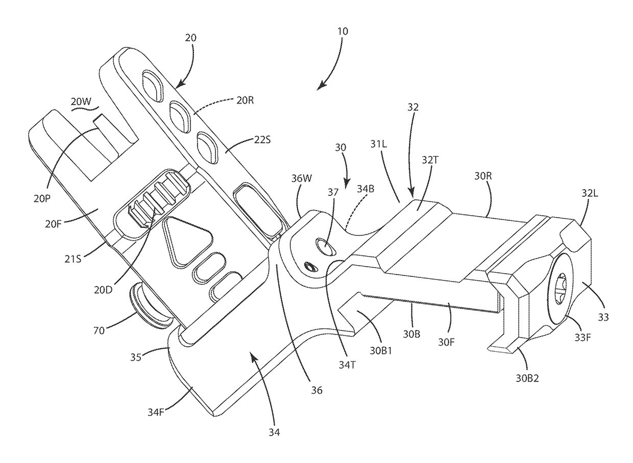
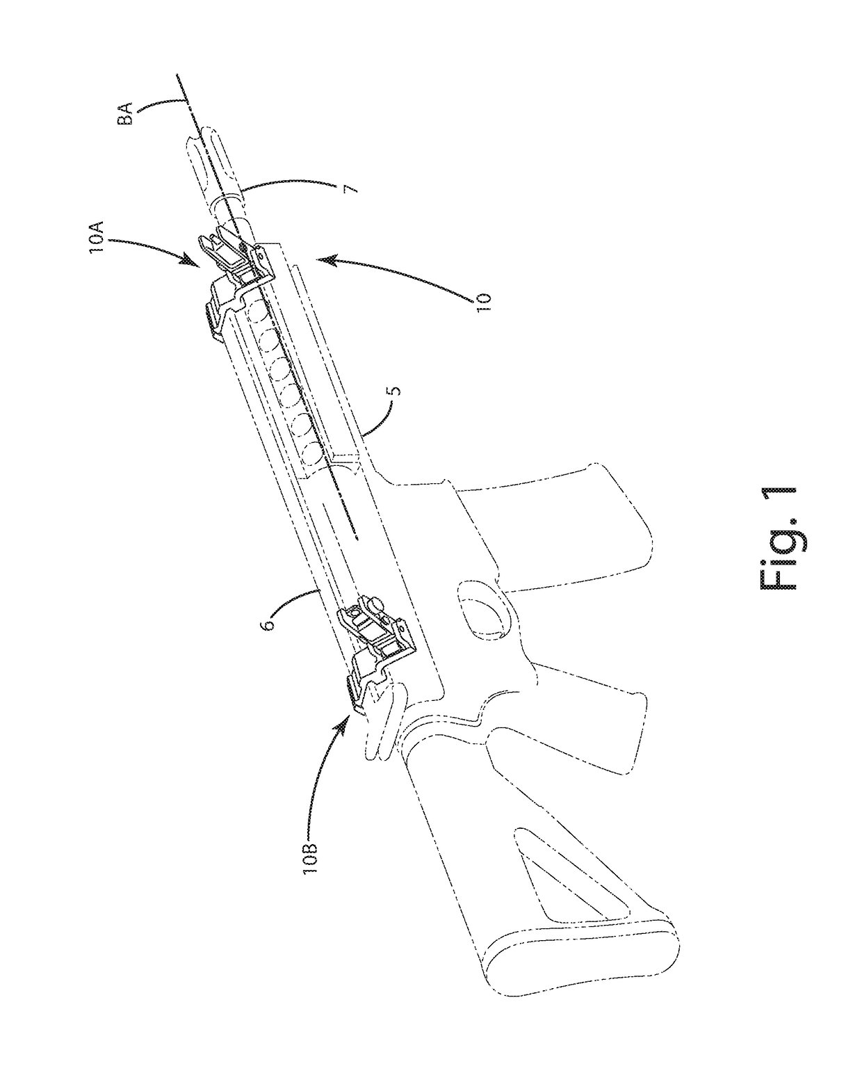
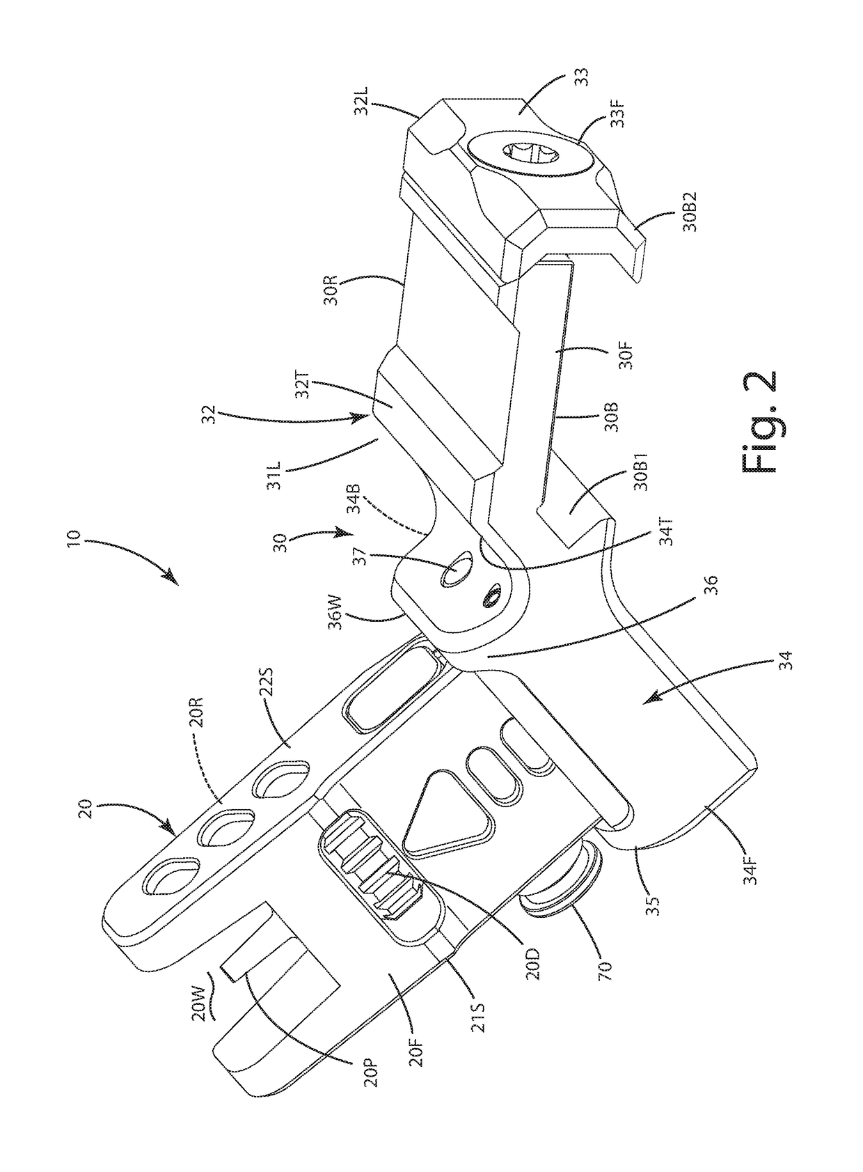
[0027]A selectively configurable sight for a firearm of the current embodiment is illustrated in FIGS. 1-8 and generally designated 10. The selectively configurable sight 10 can be implemented as front or rear sights, optionally including windage and / or elevation adjustment mechanisms. As illustrated in FIG. 1, the sight 10 can be in the form of a front sight 10A and / or a rear sight 10B, mounted along a rail 6 of the modern sporting rifle 5. The sight 10 can be utilized with any type of firearm or weapon. As described herein, the sight 10 is a front sight, but again, the current embodiments can be utilized in connection with a rear sight. Further, the sight 10 can be used with firearms, such as rifles, shotguns, handguns, artillery weapons, as well as archery equipment, such as compound bows and crossbows, or other projectile shooting devices.

[0028]With reference to FIG. 2, the sight 10 can include a sight element 20. The sight element 20 can include a front surface 20F, a rear surf...


PUM


Abstract

A firearm sight, optionally having a 45° offset mount, including a sight element selectively configurable in upright position and down positions, and a moveable plunger configurable in a locking mode in which a head of the plunger protrudes from it such that upon rotation of the sight element about a pivot axis, the head engages a plunger wall of the mount to arrest such rotation to thereby maintain the sight element substantially in the upright position, the plunger alternatively configurable in a free mode in which the head is retracted into the sight element so the head clears the plunger wall and the sight element can move to the down position. The mount can include an extension stop wall adjacent the head so the head cannot be deployed from the sight element to maintain it in the down position. The plunger can be actuated ambidextrously. A related method is provided.

Description

BACKGROUND OF THE INVENTION[0001]The present invention relates to firearms, and more particularly to a firearm sight configurable in deployed and stowed positions.[0002]Firearms can come in various shapes and sizes, and can be configured in various ways for different purposes. Many firearms are outfitted with a primary sighting system to assist a user in aligning the barrel of the firearm with a target so that a bullet fired from the firearm has a high probability of impacting the target at a desired location. Sometimes, a firearm is set up with a primary sighting system consisting of rudimentary fixed position iron sights, which include a rear sight at the rear of the firearm and a front sight over the barrel of the firearm near its muzzle. This system is configured so that the user can align the front and rear sights with one another and a target to aim the firearm. In other cases, the firearm can be outfitted with an optical sight to be used as a primary sighting system. The opti...

Claims


Application Information

Patent Timeline
Patent Type & Authority Patents(United States)
IPC IPC(8): F41G1/17F41G11/00
CPCF41G11/00F41G1/17F41G1/00F41G1/01F41G1/033
Inventor DING, TAI-LAIYU, TAT SHING
Owner LEAPERS
Why Eureka
Try Eureka