LED drive circuit

a drive circuit and drive circuit technology, applied in the direction of lighting apparatus, electrical equipment, light sources, etc., can solve the problems of not being desirable, increasing construction complexity, dimming of leds, etc., and achieves the reduction of the voltage for controlling the value of current detecting resistors, simplifying circuit configuration, and simplifying circuit configuration

US20150382420A1Active Publication Date: 2015-12-31CITIZEN WATCH CO LTD +1
0 Cites 32 Cited by

Patent Information

Authority / Receiving Office
US · United States
Current Assignee / Owner
Publication Date
2015-12-31

Smart Images

  • Figure 1
    Figure 1
  • Figure 2
    Figure 2
  • Figure 3
    Figure 3
Patent Text Reader

Abstract

The purpose of the present invention is to provide an LED drive circuit that is capable of ameliorating insufficient lighting and improving power utilization efficiency. This LED drive circuit is an LED drive circuit wherein the number of LEDs that are turned on varies in accordance with the voltage of a commercial alternating-current power supply, the LED drive circuit being characterized by having an LED row in which multiple LEDs are connected in series, a current detection resistor for detecting a current that flows in the LED row, a bypass circuit that is connected to an intermediate connection part of the LED row, and a current-limiting circuit that is connected to an end of the LED row, wherein the bypass circuit includes a first current-limiting component, the current-limiting circuit includes a second current-limiting component, the first current-limiting component is controlled on the basis of a voltage across the ends of the current detection resistor or a voltage that is obtained by dividing the voltage across the ends of the current detection resistor, and the second current-limiting component is controlled by the divided voltage that is obtained by dividing the current detection resistor.
Need to check novelty before this filing date? Find Prior Art

Description

CROSS REFERENCE TO RELATED APPLICATIONS

[0001] This is the U.S. National Phase application of PCT / JP2014 / 053787, filed Feb. 18, 2014, which claims priority to Japanese Patent Application No. 2013-028854, filed Feb. 18, 2013, Japanese Patent Application No. 2013-041683, filed Mar. 4, 2013, Japanese Patent Application No. 2013-046329, filed Mar. 8, 2013, and Japanese Patent Application No. 2013-171090, filed Aug. 21, 2013, the disclosures of each of these applications being incorporated herein by reference in their entireties for all purposes.FIELD OF THE INVENTION

[0002] The present invention relates to an LED drive circuit in which the number of LEDs driven to emit light varies according to a commercial AC power supply voltage.BACKGROUND OF THE INVENTION

[0003] It is known to provide an LED drive circuit which drives LEDs to emit light by applying a full-wave rectified waveform obtained by full-wave rectifying a commercial AC power supply to an LED array constructed by connecting a plural...

Examples

Embodiment Construction

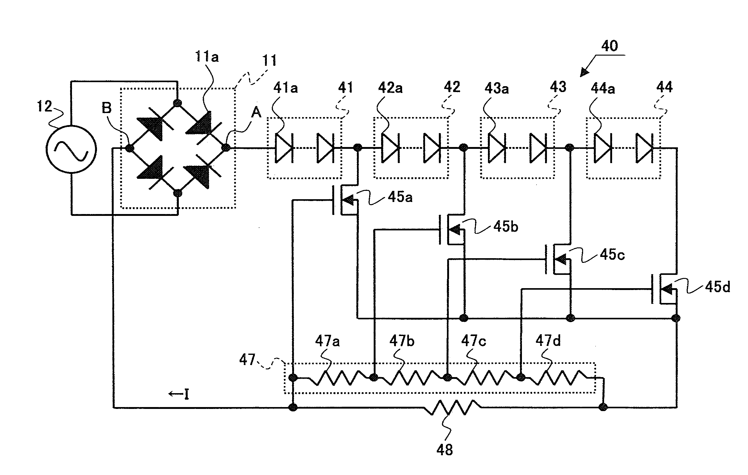
[0118]Preferred Embodiments of the Present Invention will be described below with reference to the accompanying drawings. It will, however, be noted that the technical scope of the present invention is not limited by any particular embodiment described herein but extends to the inventions described in the appended claims and their equivalents. Further, in the description of the drawings, the same or corresponding component elements are designated by the same reference numerals, and the description of such component elements, once given, will not be repeated thereafter. It will also be noted that the scale to which each component element is drawn is changed as needed for illustrative purposes.

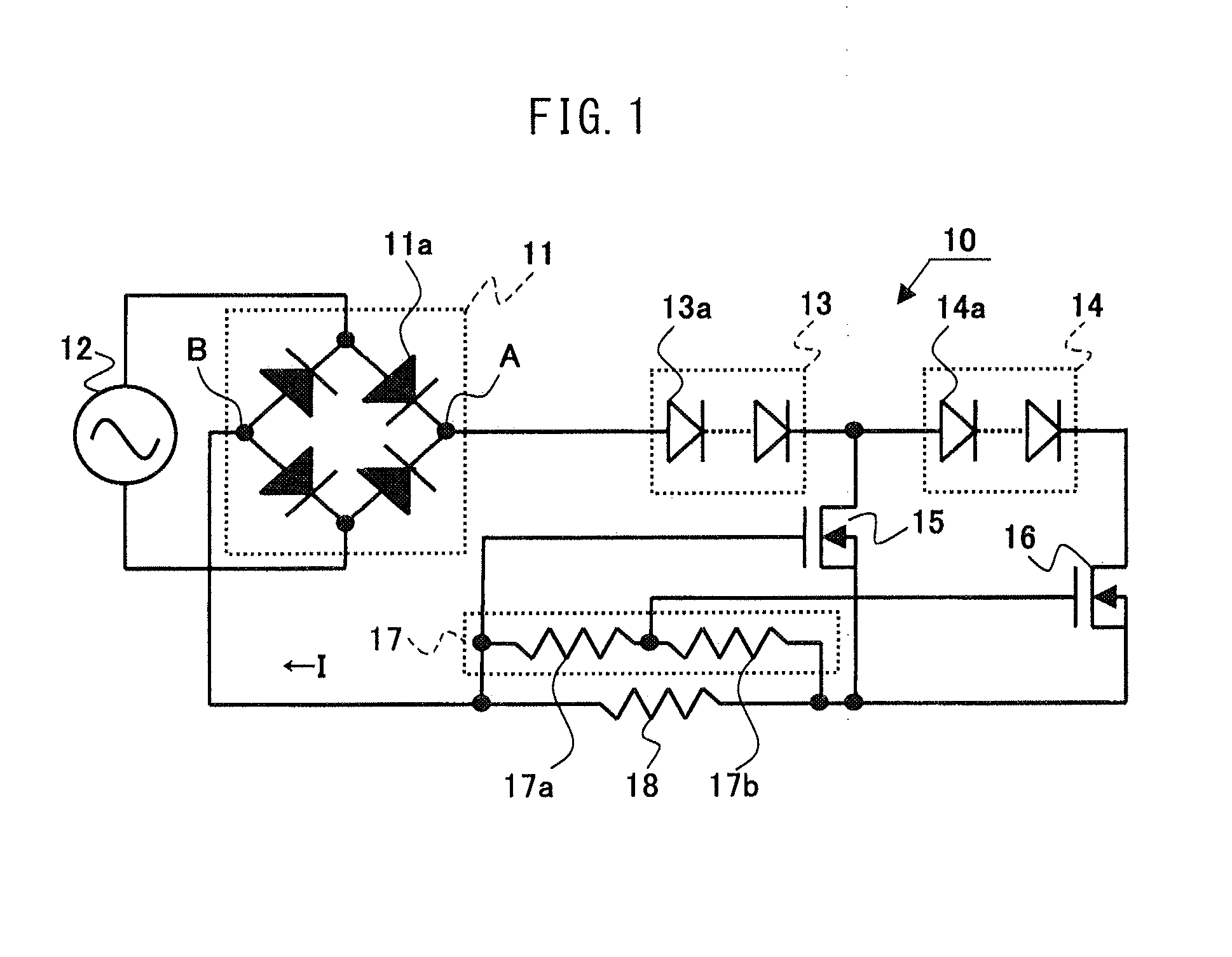
[0119]FIG. 1 is a circuit diagram of an LED drive circuit 10.

[0120]In FIG. 1, the LED drive circuit 10 comprises a bridge rectifier 11, LED sub-arrays 13 and 14, an FET 15 which is a bypass circuit as well as a current limiting device, an FET 16 which is a current limiting circuit as well as a c...